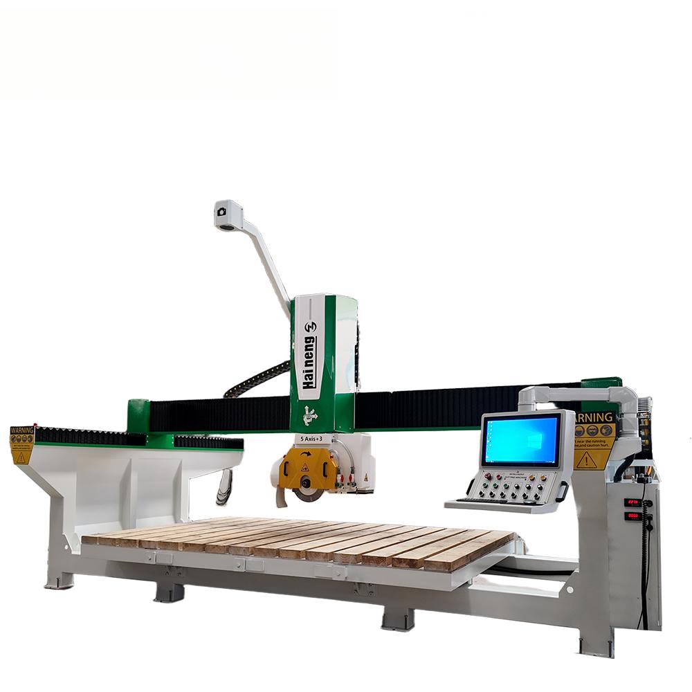
In the world of stone cutting the CNC 5 Axis Bridge Stone Cutting Machine is really something. It is changing the way people cut stone. The Stone Cutting Machine is very good at cutting stone and it can do it quickly. This Stone Cutting Machine has technology and many features that are helpful to people who work with stone. The Stone Cutting Machine can do things that people, in the stone industry need it to do. Dual Sawing Spindle Options for Versatile Operations One of the key highlights of this Bridge Cutting Machine is the availability of two types of sawing spindles. You can choose between a solid spindle and an internally water - cooled spindle, depending on your specific processing requirements. This flexibility ensures that the machine can adapt to different working conditions, optimizing performance for various stone - cutting tasks. Efficient Cooling System The water - cooled spindle is a technological marvel. With a rotating water - passing component at the tail, coolant circulates within the spindle, rapidly dissipating the heat generated during sawing. This not only cools the saw blade but also the spindle itself. Additionally, the G1/2 standard threaded interface at the spindle end allows for direct attachment of drilling pipes. Coolant can flow straight into the drill bit, preventing overheating and maintaining its long - term drilling performance. Functions for Enhanced Productivity The CNC 5 Axis Bridge Stone Cutting Machine truly shines in its one - machine - many - functions capabilities. When working on stone countertops or creating special - shaped holes like water - leakage holes, the integrated drilling components enable automatic, one - stop processing. There’s no need to transfer the workpiece to other machines, saving time and ensuring high - precision and efficient shaping. Moreover, its user - friendly operation means that one operator can manage multiple machines simultaneously, significantly reducing labor costs and boosting overall productivity. Precision in Complex Shapes and Surfaces
This Stone Cutting Machine excels at handling complex tasks. It can plan smooth and continuous processing paths for irregular curved surfaces, creating aesthetically pleasing and high - quality workpieces with excellent surface finish. For intricate structures like kitchen sink grooves and small interior corners, it achieves precise, one - step forming, mastering the most challenging stone - processing details. Whether it’s straight lines or curved arcs, the machine adheres strictly to the preset paths, ensuring standard contours and uniform surface smoothness.
Forged wheels are often associated with race cars, luxury vehicles, and high-performance builds. But many car owners have a more practical question: are forged wheels really worth it for daily driving?
The answer depends on what you expect from your wheels. If you only need a basic replacement wheel, a standard cast wheel may be enough. But if you care about strength, weight, fitment, and a cleaner custom look, forged wheels can be a meaningful upgrade even for a daily driver.
A forged wheel is made by applying high pressure to a solid piece of aluminum, rather than pouring molten aluminum into a mold like a cast wheel. This process helps create a denser and stronger wheel structure. For daily use, that strength matters. City roads, potholes, speed bumps, rough pavement, and unexpected impacts are all part of normal driving. A well-made forged aluminum wheel can offer better durability while keeping the wheel weight lower than many cast alternatives.
Weight is one of the biggest reasons drivers choose forged wheels. Lighter wheels reduce unsprung weight, which may help the suspension respond more efficiently. In real driving, this can contribute to sharper steering feel and a more responsive driving experience. The difference may not turn a daily car into a track car, but it can make the vehicle feel more refined, especially on premium sedans, SUVs, and performance models.
Another important benefit is fitment. Custom forged wheels can be made according to the vehicle’s specifications, including diameter, width, offset, bolt pattern, and brake clearance. This is especially useful for owners who want a flush stance without relying on spacers or unsuitable factory sizes. For example, many customers choose 19 inch forged wheels or 20 inch forged wheels to improve the appearance of the car while still keeping daily comfort in mind.
Appearance is also part of the value. Forged wheels are highly customizable, from spoke design to surface finish. Options such as brushed, polished, matte black, bronze, gunmetal, and two-tone finishes allow the wheel to match the style of the car. For daily drivers, this means the upgrade is not only about performance, but also about making the vehicle look more personal and premium.
Of course, forged wheels cost more than cast wheels. That is the main reason some drivers hesitate. But the higher price also reflects the material, manufacturing process, engineering work, and customization involved. If you plan to keep your vehicle for several years, or if you are building a car with specific fitment and style requirements, forged wheels can be a long-term investment rather than just a cosmetic upgrade.
So, are forged wheels worth it for daily drivers? For owners who want the lowest-cost option, they may not be necessary. But for those who value lightweight performance, stronger construction, accurate fitment, and a custom appearance, forged wheels are definitely worth considering.
At Rimpower, we manufacture custom forged wheels using T6061-T6 aluminum, with fitment support for luxury cars, SUVs, and performance vehicles. Each order can be customized based on your vehicle data, design preference, and finish requirements.
Hey, stone - working pros and DIY enthusiasts! Ever thought about how much potential lies in those seemingly useless chunks of scrap stone? Enter the Thin Stone Veneer Saw, a game - changing Natural Stone Cutting Machine and a top - tier Stone Cutter Saw that's revolutionizing the way we deal with stone waste.
Tailored for Irregular Stone Scraps
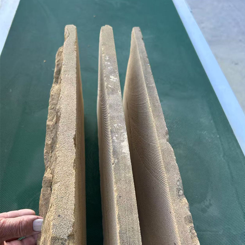
The Thin Stone Veneer Saw is no ordinary tool. Unlike large - scale bridge cutters focused on slicing big slabs from raw blocks, it's designed with a unique purpose. Its main gig? Taking those wonky - shaped, chipped - edged, and angle - off scrap stones and giving them a new lease on life.
With surgical - like precision, it cuts through the most unruly pieces. Whether it's granite, marble, or the more brittle slate and sandstone, this saw doesn't flinch. It trims and shapes, leaving behind smooth surfaces and perfect 90 - degree angles. The conveyor - belt - style feeding system makes the process seamless. No more manual re - positioning; just continuous, efficient cutting.
Turning Waste into Wealth
Natural stone is a precious, non - renewable resource. In the old days, a staggering 40 - 60% of it ended up as discarded waste. But the Thin Stone Veneer Saw is changing that narrative.
The piles of scrap stone that people used to throw are now being turned into valuable stone products. This helps use up more of our resources and it also cuts back on costs that we do not always see, like getting rid of waste renting land and cleaning up the environment. The stone waste is also helping us avoid problems, with following rules that happen when we have a lot of stone waste.
By using inexpensive scrap as raw material, you can churn out high - value finished products. It's a low - investment, high - return model that's music to any business owner's ears.
So, if you're looking to make the most of every bit of stone, the Thin Stone Veneer Saw is your go - to. It's more than just a saw; it's a sustainable solution for the stone - working industry.
If you’re a stone processor tired of discarding valuable irregular waste stones, the Irregular Stone Right Angle Cutter (your go-to Thin Stone Veneer Saw) is the game-changer you need—paired with its counterparts like the thin stone slicing saw and thin veneer cutting machine, it redefines stone waste utilization.
Patented Feeding
The biggest pain point in stone processing? Irregular scraps lack a fixed reference, making traditional machines unable to clamp them accurately. The solves this with its patented dual V-shaped adaptive feeding system: it automatically aligns and clamps any shaped waste stones without manual positioning, delivering a ±0.1mm right-angle cutting precision—turning worthless scraps directly into high-value standard decorative panels. This is the industry’s first device for "reference-free waste stone" cutting.
Maximize Profit
This Thin Stone Veneer Saw lets you process 90% of your waste: edge scraps, end scraps, irregular materials, and mine offcuts can all be loaded directly. Material utilization jumps from 30% (traditional machines) to ≥95%, turning discarded waste into sellable finished boards. Its optimized thin-plate cutting process also minimizes loss—you’ll get 3-5㎡ more boards per cubic meter of stone, slashing raw material costs by 70%+ and doubling profit margins.
Efficiency & Stability
Equipped with a high-power spindle and custom sawing system, it cuts in one pass (no repeated tool paths) and handles dozens of panels per hour—perfect for large export or engineering orders. The thickened body and imported transmission parts stand up to 24-hour continuous operation in dusty, high-load environments, with low failure rates to keep production on track. Plus, the adjustable cutting parameters adapt to 5-100mm thicknesses and various stones (granite, marble, etc.).
Easy Operation & Global Compatibility The PLC touch control system is user-friendly—newbies can master it quickly—while the integrated return conveyor automates cutting and conveying, requiring only 1 worker (halving labor costs). It also has multiple safety protections (emergency stop, full enclosure) and fits small factories with its compact design. Supporting global voltages and meeting CE/ISO standards, it’s ready for export worldwide.
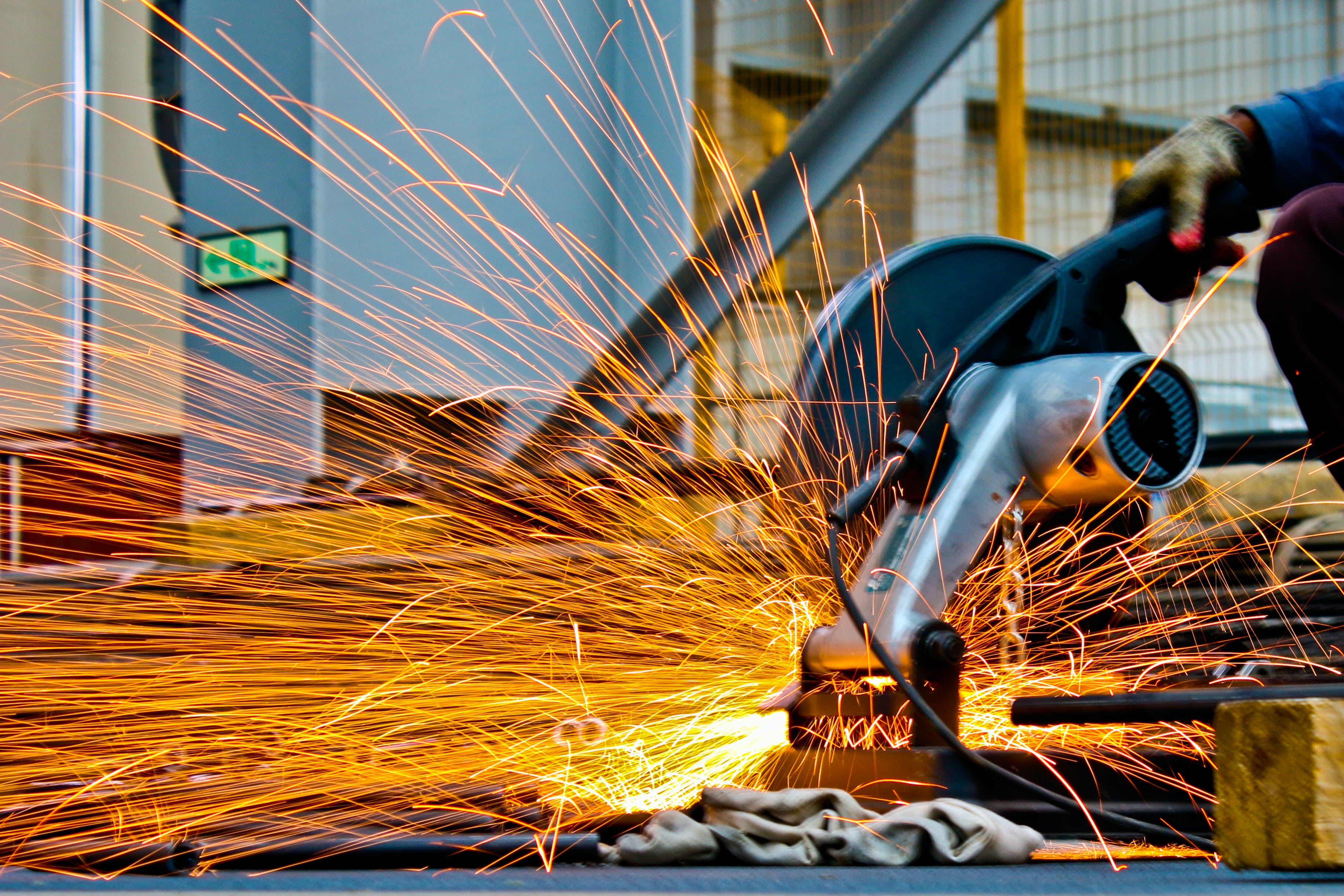
In the fast-paced world of construction, precision is everything. Even veteran operators can occasionally overlook a critical detail: the rotation direction of a diamond blade. If you find your brand-new blade cutting at a snail’s pace or generating excessive sparks, the first thing to check is—is it mounted correctly?
The Science of Unidirectional Design Diamond blades are more than just steel discs. The segments consist of diamond crystals embedded in a metal bond matrix. During the factory "sharpening" process, a microscopic "tail" forms behind each diamond particle. Think of these as tiny support structures for the cutting edge.
When a blade spins in reverse, the impact force hits the diamond crystals from the unsupported side. This leads to:
Diamond Glazing: The crystals get polished smooth rather than biting into the material. Extreme Overheating: Friction increases exponentially, softening the metal bond.
Segment Loss: For non-laser-welded blades, reverse stress can cause segments to fly off, posing a major safety hazard.
How to Identify the Correct Direction on a SANG Blade Follow the Arrow: Every SANG blade features a clearly laser-etched or printed arrow on the steel core. Ensure this aligns with the arrow on your machine's safety guard. Inspect the "Diamond Tails": If the markings have worn off, look at the segments with a magnifying glass. The "comet tail" trail behind the diamond grit indicates the direction opposite to the rotation. Summary: Never Compromise on Direction Mounting a blade backwards can reduce cutting efficiency by 80% and cut the tool’s lifespan in half within minutes. Always double-check before you pull the trigger.
For many shipowners and offshore project contractors, the biggest concern when selecting a cooling system is not the cooling capacity itself — it is whether the equipment can survive the environment.
High salt concentration, humid air, continuous vibration, and 24-hour operation create conditions that are far more demanding than ordinary industrial factories. A standard chiller that performs well indoors may begin showing corrosion, electrical instability, or efficiency loss within a surprisingly short time after being deployed offshore. So, can marine chillers really operate reliably in these conditions?
From our experience at Hengde Chiller, the answer is yes — but only if the system is designed specifically for marine environments rather than simply adapted from a standard industrial chiller.
Salt Air Damages Equipment Faster Than Many Users Expect
One thing many first-time marine project buyers underestimate is that salt corrosion does not only affect the external metal casing.
In reality, salt-laden air slowly enters almost every part of the system, including electrical terminals, condenser fins, copper joints, fan motors, and even sensor connections. Over time, this can create oxidation layers that reduce conductivity and cooling efficiency.
In many offshore projects, the earliest failures are often not compressors or refrigerant systems — they are small electrical connection points and terminals that gradually corrode because of moisture mixed with salt particles. This is why professional marine chillers usually place heavy focus on electrical protection, not just refrigeration performance.
At Hengde, marine chillers are typically equipped with:
Corrosion-resistant structural materials
Protective coatings for metal components
Moisture-resistant electrical cabinet design
Reinforced piping protection
Stable control systems for continuous operation
These details may seem minor during purchasing, but they become critical after several months of offshore use.
Humidity Is Sometimes More Dangerous Than Seawater
Most people immediately think about seawater corrosion when discussing marine cooling systems. However, in practical operation, humidity itself can become an even bigger hidden risk.
When humid air enters electrical cabinets and meets temperature differences caused by cooling systems, condensation can form inside the equipment. Once moisture accumulates on electrical components, unstable signals and unexpected shutdowns may occur.
In coastal environments, repeated condensation inside electrical cabinets is often more harmful than occasional seawater exposure because operators may not notice the issue until electrical faults begin appearing intermittently. This is one reason marine chillers require better sealing and ventilation design compared with standard industrial chillers.
Stable Operation Matters More Than Extreme Cooling Capacity
Some buyers focus heavily on achieving the lowest possible temperature. But in marine applications, stability is usually more important than extreme cooling performance. A marine chiller running continuously at moderate, stable conditions will generally outperform a system constantly pushed near its maximum operating limit.
For offshore projects, slightly oversized chillers often achieve longer service life because the compressor operates under lower stress during continuous operation. This is especially important on vessels or offshore platforms where maintenance opportunities are limited.
At Hengde, many customers prefer customized marine chillers with operating margins built into the design, especially for tropical coastal regions where ambient temperatures and humidity remain high year-round.
Vibration Is an Overlooked Problem Offshore
Unlike factory installations on stable concrete floors, marine chillers often operate under constant vibration caused by engines, waves, and platform movement. Over time, vibration may loosen piping connections, damage support brackets, or increase mechanical wear.
In real marine installations, poor piping support design can sometimes create more long-term reliability problems than the refrigeration system itself. Because of this, marine chillers often require reinforced internal structures and vibration-resistant installation methods.
Common Marine Chiller Applications
Today, marine chillers are widely used in:
Ship engine cooling systems
Offshore drilling platforms
Hydraulic equipment cooling
Seawater desalination projects
Seafood processing plants
Coastal chemical facilities
Marine battery cooling systems
Different projects require different cooling capacities, anti-corrosion levels, and voltage standards, which is why customized solutions are becoming increasingly common in the marine industry.
As a professional manufacturer, Hengde supports OEM and ODM marine chiller solutions based on customer installation space, operating conditions, and environmental requirements.
FAQ
FAQ 1: Can marine chillers use seawater directly?
Yes, but special materials are usually required. Standard condensers may corrode quickly when exposed directly to seawater. For seawater cooling applications, titanium heat exchangers or specially treated corrosion-resistant condensers are commonly recommended.
Generally, yes. Marine environments are naturally harsher than indoor industrial environments. However, properly designed marine chillers can still maintain long-term stable operation if operators regularly:
Clean heat exchangers
Check anti-corrosion coatings
Inspect electrical connections
Remove salt buildup
Monitor refrigerant conditions
Preventive maintenance is especially important for offshore equipment because emergency repairs at sea are significantly more expensive.
Real Project Case: How Hengde Helped a Maldives Customer Solve Fishing Vessel Cooling Problems
Hengde worked with a customer from the Maldives who operated several local fishing vessels. The customer originally used conventional industrial chillers purchased through a local supplier, but after less than a year of operation, multiple problems began appearing.
The biggest issues included:
Severe corrosion on condenser fins
Frequent electrical alarms during humid weather
Unstable cooling performance after continuous operation
Rust around piping connections and mounting structures
Because the vessels operated in high-salt seawater environments almost every day, the standard chillers simply could not withstand the local conditions. After discussing the operating environment with the customer, Hengde redesigned the system specifically for marine use. The upgraded solution included:
Enhanced anti-corrosion protection
More suitable condenser materials for coastal operation
Reinforced electrical cabinet sealing
Improved vibration resistance for onboard installation
More stable temperature control during continuous sailing operations
For marine applications like fishing vessels, space is always extremely limited. In many cases, the design of a marine chiller has to be significantly more compact than land-based industrial chillers. This is not just an aesthetic choice — it is a practical requirement driven by ship layout constraints, where every cubic meter of space directly affects storage capacity and operational efficiency. After the new marine chillers were installed, the customer reported much more stable operation during daily fishing activities, especially during long working hours in tropical weather conditions.
For marine projects, real reliability does not come from having the most complex system. It comes from understanding how offshore environments and vessel limitations gradually affect equipment design — and optimizing the system from the start around those realities.
As fundamental machinery in mechanical processing, lathes machine are widely used across numerous manufacturing sectors of the national economy due to their ability to machine rotary parts efficiently and with high precision. They are vital equipment underpinning industrial production, with applications spanning a wide range of production requirements from general-purpose components to high-end precision parts.
In the automotive manufacturing industry, lathes occupy a central position in the machining process. A vast number of shaft-type, disc-and-sleeve-type and threaded parts in automotive engines, gearboxes and chassis systems require machining on lathes, such as crankshafts, camshafts, drive shafts, half-shafts, wheel hubs, valves, bushings and bearing housings. Given the characteristics of automotive components namely high production volumes and stringent precision requirements CNC lathes enable automated continuous production, ensuring dimensional consistency and assembly accuracy, thereby providing a reliable guarantee for the performance of the complete vehicle.
In the general machinery and equipment manufacturing sectors, lathes are indispensable basic machining equipment. Standard components and transmission parts of all kinds such as gearbox shafts, gear shafts, couplings, flanges, bolts and pins rely on lathes for the machining of external circles, end faces, grooves and threads. Whether in small mechanical equipment or large industrial machinery, the core rotating components are generally subjected to rough and finish machining on lathes to meet the requirements for equipment assembly and operation.
In the hydraulic, pneumatic and mould industries, lathes are primarily responsible for the machining of precision-fit components. Hydraulic and pneumatic components, such as cylinder barrels, piston rods, valve spools, valve stems and pipe fittings, demand extremely high precision in sealing and mating surfaces; lathes ensure their roundness, cylindricity and surface finish. The mould industry utilises lathes to machine precision parts such as guide pins, guide bushings, ejector pins and mould cores, ensuring smooth mould opening and closing, precise fit, and enhancing mould service life and moulding quality.
In the aerospace and high-end equipment sectors, lathes are frequently used to machine high-precision, high-performance critical components. Examples include aircraft engine shafts, aerospace instrument housings, flanges and precision threaded fasteners. As these parts are made from specialised materials and subject to stringent tolerances, high-precision CNC lathes enable the machining of complex rotary surfaces and precision threads, thereby meeting the exacting standards for strength, stability and reliability demanded by aerospace products.
Furthermore, lathes are equally widely used in sectors such as hardware tools, medical devices, agricultural machinery and construction machinery. Components in hardware tools such as drill shanks, wrench handles and sockets as well as surgical instrument shafts, orthopaedic implants and precision bushings in medical devices, alongside drive shafts for agricultural machinery and pin bushings for construction machinery, all rely on lathe machining.
With the advancement of CNC technology, lathes are evolving towards higher speeds, greater precision and automation. They are not only suitable for high-volume assembly line production but can also meet the demands of small-batch, multi-variety precision component machining. By continuing to provide critical component support across various industries, they serve as essential foundational equipment for the development of modern manufacturing.
Selecting between vertical and horizontal machining centers requires comprehensive analysis of production requirements, material characteristics, and manufacturing workflows for optimal equipment investment. Understanding the fundamental differences in vertical machining center and horizontal configurations enables manufacturers to align equipment capabilities with specific operational needs and production objectives. Proper evaluation following a vertical vs horizontal machining center selection guide ensures long-term productivity, accuracy, and return on investment in competitive manufacturing environments.
Structural Design and Configuration
Vertical machining centers feature vertically oriented spindles that provide excellent visibility and accessibility for operators during setup and monitoring of machining operations. Horizontal machining centers utilize horizontally oriented spindles that offer superior chip evacuation and multi-sided machining capabilities in automated production environments. The vertical CNC machining center configuration typically requires less floor space while providing easier tool access for maintenance and changeover procedures in diverse manufacturing applications.
Workpiece Handling and Setup
Vertical machining centers excel in processing flat or cubic workpieces where tool access primarily occurs from above the workpiece on stationary or rotary tables. Horizontal machining centers better accommodate multi-sided machining requirements through integrated pallet systems that enable parallel processing of multiple workpieces. Understanding your specific workpiece geometry and fixturing requirements represents the first critical step in any effective vertical vs horizontal machining center selection guide methodology.
Accuracy and Surface Finish
Vertical machining centers typically deliver excellent surface finish quality on horizontal surfaces due to optimal tool engagement angles and cutting force directions during machining operations. Horizontal machining centers provide superior accuracy on vertical surfaces with reduced tool deflection and improved stability during side-wall machining applications. Modern vertical CNC machining centers incorporate advanced thermal compensation that maintains precision throughout extended production runs regardless of orientation or configuration.
Tooling System Considerations
Vertical machining centers generally offer simpler tool changing mechanisms with straightforward access to tool magazines and reduced tool interference concerns during operations. Horizontal machining centers accommodate larger tool capacities with specialized tooling arrangements that support complex machining sequences and extended unattended operations. The vertical CNC machining center configuration facilitates quick tool inspection and measurement due to accessible tool mounting positions and visible tool condition monitoring.
Automation Integration Potential
Vertical machining centers increasingly integrate with robotic loading systems that leverage their open workspace configuration for efficient material handling in automated manufacturing cells. Horizontal machining centers traditionally support advanced pallet changing systems that enable continuous production through parallel setup and machining operations. Understanding automation requirements early in the selection process following a comprehensive vertical vs horizontal machining center selection guide ensures future manufacturing flexibility.
Space Utilization and Facility Planning
Vertical machining centers typically require less floor space for equivalent work envelope capabilities compared to horizontal configurations with similar machining capacities. Horizontal machining centers demand more extensive facility planning to accommodate pallet systems, chip conveyors, and associated automation equipment in production environments. The vertical CNC machining center installation often simplifies facility modifications through straightforward foundation requirements and reduced overhead clearance needs.
Cost Analysis and Investment Planning
Initial acquisition costs for vertical machining centers generally remain lower than comparable horizontal configurations with similar precision and power capabilities. Horizontal machining centers often deliver higher long-term productivity through reduced non-cutting time and enhanced automation capabilities in high-volume manufacturing scenarios. A comprehensive vertical vs horizontal machining center selection guide must include total cost of ownership calculations encompassing equipment, tooling, fixturing, and operational expenses.
Material and Industry Applications
Vertical machining centers excel in die and mold manufacturing where complex 3D contours and deep cavity machining benefit from vertical spindle orientation and visibility. Horizontal machining centers dominate in automotive and aerospace industries where multi-sided machining of prismatic components requires efficient pallet handling and extended unmanned operations. The vertical CNC machining center demonstrates particular advantages in general machining applications where flexibility and quick changeovers outweigh maximum production volume requirements.
Maintenance and Service Accessibility
Vertical machining centers provide excellent component accessibility for routine maintenance procedures with straightforward access to spindles, drives, and control systems. Horizontal machining centers require specialized maintenance approaches for pallet changers, rotary tables, and integrated automation systems that experience distinct wear patterns. Regular maintenance scheduling differs significantly between configurations as detailed in comprehensive vertical vs horizontal machining center selection guide documentation.
Technology Development Trends
Vertical machining centers increasingly incorporate five-axis capabilities that expand their application range while maintaining the inherent advantages of vertical spindle orientation. Horizontal machining centers continue advancing in automation integration with smarter pallet systems and enhanced connectivity for Industry 4.0 manufacturing environments. The vertical CNC machining center evolves through improved accuracy standards and expanded software capabilities that enhance programming efficiency and operational flexibility.
Implementation Strategy Development
Phased implementation approaches optimize the transition between different machining center configurations in established manufacturing operations with minimal production disruption. Comprehensive operator training programs ensure maximum utilization of selected equipment whether implementing vertical machining centers or horizontal alternatives. Performance monitoring and continuous improvement processes refine equipment selection criteria based on actual production experience and evolving manufacturing requirements.
Conclusion and Strategic Recommendations
Informed machining center selection requires balanced evaluation of technical specifications, production requirements, and strategic manufacturing objectives using a proven vertical vs horizontal machining center selection guide. Specific application characteristics should drive final configuration decisions rather than generalized preferences or traditional industry practices in modern manufacturing environments. Continuous technology assessment ensures manufacturing facilities maintain optimal equipment configurations as both vertical and horizontal machining center technologies advance in capability and efficiency.
High speed milling machines revolutionize aluminum alloy processing by dramatically reducing cycle times while improving surface finish quality in modern metal machining operations. Modern CNC milling machine technology enables unprecedented cutting speeds that maximize material removal rates while maintaining dimensional accuracy in aluminum components. Understanding how to choose between vertical and horizontal milling machine configurations ensures optimal equipment selection for specific aluminum processing requirements and production volumes.
High Speed Technology Fundamentals
High speed milling machines achieve spindle speeds exceeding 15,000 RPM specifically optimized for aluminum's excellent machinability characteristics in precision milling applications. Advanced CNC milling machine controls maintain optimal cutting parameters through real-time adjustments that prevent tool deflection and maintain accuracy at elevated feed rates. The vertical milling machine configuration particularly benefits aluminum processing through superior chip evacuation and stable workholding during high-speed metal machining operations.
Aluminum Processing Advantages
Aluminum's low cutting resistance enables exceptional high speed milling machine for aluminum efficiency benefits with material removal rates often triple those achievable with standard milling equipment. Specialized tooling geometries maximize chip formation efficiency while minimizing heat generation during extended precision milling operations on aluminum components. Modern CNC milling machine systems incorporate thermal management technologies that maintain consistent accuracy throughout high-volume aluminum metal machining production cycles.
Precision and Quality Enhancement
High speed milling delivers superior surface finishes on aluminum components reducing or eliminating secondary finishing operations in precision milling applications. Multi-axis CNC milling machine capabilities enable complex aluminum geometries to be machined in single setups, minimizing handling and improving dimensional consistency. The vertical milling machine provides excellent accessibility for aluminum components with shallow profiles that benefit from overhead tool access during metal machining operations.
Production Efficiency Optimization
Reduced cycle times represent the primary high speed milling machine for aluminum efficiency benefits with machining durations often decreasing by 40-60% compared to conventional milling approaches. Automated tool changing and workpiece handling systems maximize spindle utilization in high-volume aluminum processing environments using advanced CNC milling machine technology. Understanding how to choose between vertical and horizontal milling machine configurations becomes crucial when optimizing production flow for specific aluminum component geometries and batch sizes.
Tooling Technology Innovations
Specialized aluminum cutting tools feature optimized flute designs that efficiently evacuate chips during high speed milling operations, preventing recutting and heat buildup. Modern CNC milling machine systems support advanced tool monitoring that detects developing wear patterns before they impact aluminum component quality in precision milling applications. The vertical milling machine's gravity-assisted chip removal significantly enhances tool life and cutting performance in continuous aluminum metal machining operations.
Energy Efficiency Considerations
High speed milling machines optimize power consumption by completing aluminum processing operations more quickly than conventional equipment, reducing overall energy usage per component. Advanced CNC milling machine drives incorporate regenerative braking technology that recovers energy during spindle deceleration in aluminum precision milling cycles. Modern vertical milling machine designs minimize parasitic energy losses through efficient cooling systems and optimized structural dynamics during high-speed metal machining operations.
Process Integration Strategies
High speed milling seamlessly integrates with upstream and downstream processes in aluminum component manufacturing, supporting lean production methodologies and reduced work-in-progress. Multi-axis CNC milling machine capabilities eliminate secondary operations by completing complex aluminum features in single setups, streamlining production flow in metal machining facilities. Understanding how to choose between vertical and horizontal milling machine options facilitates optimal equipment arrangement within aluminum processing cells for maximum productivity.
Quality Control Integration
In-process measurement systems maintain dimensional accuracy throughout high speed milling operations on aluminum components, enabling immediate correction of developing deviations. Modern CNC milling machine controls record comprehensive process data for each aluminum component manufactured, supporting traceability requirements in regulated industries. The vertical milling machine configuration facilitates easy access for measurement probes during aluminum precision milling operations, minimizing interruption to production flow.
Material Utilization Optimization
High speed milling enables aggressive machining strategies that maximize material removal from aluminum blanks while maintaining component integrity and dimensional accuracy. Advanced CNC milling machine programming optimizes tool paths to minimize air cutting and non-productive movements in aluminum metal machining operations. The high speed milling machine for aluminum efficiency benefits includes reduced material waste through precise stock allowance management and optimized cutting approaches.
Maintenance and Reliability
Specialized maintenance protocols ensure consistent performance of high speed milling machines processing aluminum, addressing unique wear patterns associated with elevated cutting parameters. Modern CNC milling machine designs incorporate preventive maintenance features that alert operators to developing issues before they impact aluminum processing productivity. The vertical milling machine's accessible component arrangement simplifies maintenance procedures while minimizing downtime in continuous aluminum metal machining operations.
Global Manufacturing Applications
Aluminum component manufacturers worldwide standardize on high speed milling processes to maintain competitive production efficiency and quality consistency across global operations. Understanding regional variations in aluminum alloys and processing requirements informs optimal CNC milling machine selection and parameter optimization strategies. The high speed milling machine for aluminum efficiency benefits translates across international markets through standardized processing approaches that ensure consistent component quality regardless of manufacturing location.
Future Technology Development
Emerging milling technologies continue enhancing aluminum processing efficiency through improved cutting tools, advanced control algorithms, and innovative machine designs. CNC milling machine capabilities will expand through AI-enhanced optimization that automatically adjusts parameters based on real-time aluminum material behavior during precision milling operations. Sustainable manufacturing initiatives will influence high speed milling development with energy recovery systems and reduced environmental impact in aluminum metal machining processes.
Implementation Best Practices
Comprehensive process validation ensures optimal high speed milling results with aluminum materials, verifying cutting parameters and tooling selections before full-scale production. Phased implementation approaches minimize disruption to existing aluminum processing while gradually optimizing CNC milling machine performance for specific component requirements. Continuous operator training programs maximize high speed milling utilization through proper technique development and process understanding in aluminum metal machining applications.
Conclusion and Strategic Recommendations
High speed milling technology delivers transformative efficiency advantages in aluminum alloy processing through reduced cycle times, improved surface quality, and enhanced dimensional accuracy. Proper CNC milling machine selection and configuration optimization ensures maximum realization of high speed milling machine for aluminum efficiency benefits in specific production environments. Ongoing technology assessment and process refinement maintain competitive advantage as aluminum materials, component designs, and manufacturing requirements continue evolving across global industries.
A heavy duty lathe is one of the biggest investments in any machine shop. These machines can weigh 50 tons or more and cost hundreds of thousands of dollars. They're built to last decades—but only if you take care of them. This guide covers everything you need to know about keeping your heavy duty lathe running like new.
Why Maintenance Matters More on Heavy Lathes
When a 30-ton lathe breaks, the repair crew comes to you—and the clock is ticking. Lost production, expensive service calls, costly parts, scrapped workpieces from accuracy loss, and safety risks all add up fast. Prevention is always cheaper than repair.
Daily Maintenance (15 Minutes)
Start every day with these checks. Clean the machine thoroughly—chips are the enemy. They get into ways, damage precision surfaces, and cause wear. Check all oil reservoirs; low oil means rapid wear. If the automatic lubrication system isn't working, fix it immediately. Inspect the chuck to ensure all jaws move freely and it's tight on the spindle—a loose chuck is dangerous. Warm up the spindle at low speed for 10-15 minutes before heavy cutting. This lets oil reach all bearings and allows the machine to reach thermal stability. Finally, check for any new damage and listen for unusual sounds when moving axes.
Weekly Maintenance (1-2 Hours)
Once a week, inspect all way surfaces for scoring or wear. Check way wipers—they should be tight against the ways; replace if worn. Check spindle runout with a dial indicator and record the reading. Sudden increase means bearing problems. Test tailstock alignment using a test bar—misalignment causes tapered work. Check all bolts and fasteners as heavy cutting loosens things over time. Inspect drive belts for cracks or wear, and check tension. If your lathe has hydraulic systems, check oil level and pressure and look for leaks. Verify coolant concentration and level—bad coolant needs changing.
Monthly Maintenance (Half Day)
Once a month, check gearbox oil for metal particles and change if dirty. Inspect all electrical connections—loose connections overheat and fail. Clean electrical cabinet filters. Measure axis backlash in cross slide and carriage; increasing backlash means wear in lead screws or half nuts. Lubricate all manual grease fittings. Clean and inspect steady rests and follow rests, adjusting if needed. Remove the chuck if possible to inspect spindle nose and mounting surface. Test all safety devices including emergency stops and limit switches.
Yearly Maintenance (1-2 Days)
Once a year, change all oils—hydraulic, gearbox, and way oil. Old oil loses additives and carries wear particles. Replace all filters. Use precision levels and test bars to verify bed level, headstock alignment, tailstock alignment, carriage squareness, and lead screw accuracy. Listen to spindle bearings with a mechanics stethoscope at various speeds—roughness means replacement soon. Check half nuts and lead screw for wear. Adjust all gibs and check for wear steps on ways. Replace any leaking seals. Calibrate DRO or CNC scales if equipped.
Common Problems and Fixes
Chatter during cutting? Check workpiece support, tool condition and overhang, gib adjustments, and spindle bearings. Tapered cuts? Check tailstock alignment, headstock alignment, bed level, and way wear. Rough finish? Check tool condition, spindle bearings, vibration sources, and speed/feed selection. Carriage hard to move? Check way lubrication, gib adjustment, debris under wipers, and rack and pinion wear. Chuck won't hold tight? Clean chuck jaws and scroll, check hydraulic pressure, check for worn jaws, and verify chuck mounting bolts. Unusual noises? Grinding means check lubrication, knocking means check gears or bearings, squealing means check belts, rubbing means check for debris or misalignment.
Special Considerations for Older Machines
Many heavy duty lathes run for 50+ years. Old iron is often more rigid than new machines, so don't replace just because it's old. Watch for wear more frequently and check alignment more often. Add DRO for better accuracy, new chuck for better grip, or coolant system if missing. For very old machines, parts may be hard to find—keep spares if possible and build relationships with machine rebuilders. Know that older machines may not hold today's tight tolerances without extra care, so work within their capability.
Training Your Team
The best maintenance program fails if operators don't follow it. Teach daily checks and explain why each matters. Build maintenance time into the schedule—don't rush to start cutting. Encourage reporting of anything unusual; early detection prevents major failures. Keep written records of every check, problem, and fix—this history helps spot trends. Build a relationship with trusted service providers for annual inspections and major repairs.
Bottom Line
A heavy duty lathe is a long-term asset. With proper care, it will serve your shop for decades. Without care, it will fail early and cost you dearly. A few hours of maintenance per month prevents weeks of downtime and thousands in repairs. A clean, well-lubricated, properly adjusted machine makes better parts and makes them longer. Treat your heavy lathe like the investment it is, and it will give you the production you need—every day, for decades.