头部背景图片

How to Choose CNC Gantry Milling Machines for Large Part Manufacturing?

2026-04-30

Introduction


Selecting the right CNC gantry milling machine requires systematic analysis of technical specifications and production requirements for optimal large part machining performance. Understanding the complexities of comparing different gantry milling machine configurations enables manufacturers to make informed investment decisions aligned with specific operational needs. Proper evaluation of gantry milling machine foundation installation specifications ensures long-term accuracy and stability in demanding industrial machining applications.


Technical Specification Analysis


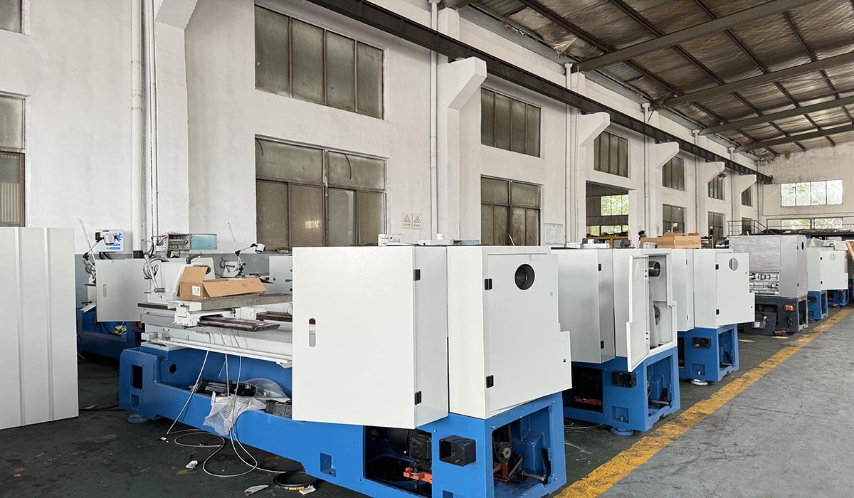
CNC gantry milling machines must match specific workpiece dimensions and material characteristics through careful evaluation of table sizes, travel ranges, and spindle capabilities. 5 axis gantry milling machine configurations provide enhanced geometric flexibility but require detailed assessment of additional axis requirements for complex large part machining applications. Comparing different gantry milling machine configurations involves analyzing structural designs including fixed versus moving gantry arrangements based on specific manufacturing requirements.


Structural Configuration Considerations


Fixed gantry milling machines offer superior rigidity for heavy-duty machining while moving gantry designs provide extended work envelope capabilities in gantry machine applications. Understanding the implications of gantry milling machine foundation installation specifications becomes crucial when selecting between different structural configurations for large part machining operations. Modern CNC gantry milling machines incorporate advanced compensation technologies that maintain accuracy across various structural designs in demanding industrial environments.


Spindle Technology Evaluation


High-torque spindles enable efficient material removal in large part machining applications where heavy cutting forces challenge conventional CNC gantry milling machines. High-speed spindles benefit aluminum and composite material processing in 5 axis gantry milling machine applications requiring superior surface finishes and reduced cycle times. Comparing different gantry milling machine configurations includes spindle power analysis based on material characteristics and production volume requirements in gantry machine operations.


Control System Requirements


Advanced CNC systems enable complex programming capabilities essential for optimizing 5 axis gantry milling machine performance in sophisticated large part machining applications. Multi-channel control configurations support simultaneous machining operations in high-productivity CNC gantry milling machine installations requiring maximum equipment utilization. Integrated measurement and compensation systems maintain precision regardless of structural configuration differences in comparing different gantry milling machine options.


Accuracy and Precision Standards


Laser calibration verification ensures positional accuracy meets manufacturing requirements when selecting CNC gantry milling machines for precision large part machining. Thermal compensation systems counteract environmental variations that could impact 5 axis gantry milling machine performance in facilities with significant temperature fluctuations. Repeatability testing validates consistent performance across different gantry milling machine configurations under actual production conditions.


Foundation and Installation Planning


Detailed evaluation of gantry milling machine foundation installation specifications prevents future accuracy issues caused by inadequate support structures in CNC gantry milling operations. Soil analysis and vibration isolation requirements vary when comparing different gantry milling machine configurations with distinct structural characteristics and mass distributions. Professional installation services ensure proper alignment and long-term stability for both standard CNC gantry milling machines and specialized 5 axis configurations.


Automation Integration Potential


Pallet changing systems enhance productivity in CNC gantry milling machine applications requiring minimal setup time between different large part machining operations. Robotic loading integration requires specific structural considerations when comparing different gantry milling machine configurations for automated manufacturing cells. Tool management systems optimize cutter utilization in both standard and 5 axis gantry milling machine installations through organized storage and automatic retrieval capabilities.


Material Handling Requirements


Workpiece weight capacities determine structural specifications when selecting CNC gantry milling machines for heavy large part machining applications. Overhead crane compatibility influences machine placement decisions based on gantry milling machine foundation installation specifications and facility logistics. Loading system integration requires careful planning in comparing different gantry milling machine configurations with varying accessibility and work envelope characteristics.


Maintenance and Service Considerations


Preventive maintenance programs extend equipment lifespan for both standard CNC gantry milling machines and specialized 5 axis configurations in demanding large part machining environments. Service accessibility differs significantly when comparing different gantry milling machine configurations requiring tailored maintenance approaches based on structural designs. Spare parts availability and technical support networks influence long-term operational success in CNC gantry milling machine investments.


Cost-Benefit Analysis Framework


Total cost of ownership calculations include foundation expenses detailed in gantry milling machine foundation installation specifications for accurate investment comparisons. Productivity improvements justify premium features in 5 axis gantry milling machine configurations through reduced setup times and enhanced machining capabilities. Return on investment projections should compare multiple configurations when evaluating different gantry milling machine options for specific large part machining applications.


Future Technology Compatibility


Upgrade pathways differ when comparing different gantry milling machine configurations with varying capacities for incorporating emerging technologies in CNC gantry milling operations. Software compatibility ensures long-term relevance of both standard and 5 axis gantry milling machine investments as manufacturing technologies evolve. Modular designs facilitate technology integration in CNC gantry milling machines, supporting future expansion and capability enhancements in large part machining applications.


Industry-Specific Requirements


Aerospace manufacturing demands exceptional precision from 5 axis gantry milling machine configurations for complex component geometries in large part machining operations. Energy sector applications require heavy-duty capabilities from CNC gantry milling machines processing oversized components for power generation equipment. Comparing different gantry milling machine configurations must consider industry standards and certification requirements specific to various manufacturing sectors.


Conclusion and Implementation Strategy


Systematic selection processes ensure optimal CNC gantry milling machine investments through comprehensive analysis of technical specifications and operational requirements. Professional consultation addresses complex considerations in comparing different gantry milling machine configurations and foundation requirements for large part machining applications. Continuous performance monitoring validates selection decisions and informs future equipment investments as manufacturing requirements evolve in competitive global markets


How to Maintain Your Gantry Milling Machine for Maximum Longevity and Precision?

2026-04-30

Introduction

Proper maintenance of your CNC gantry milling machine is essential for preserving its precision and extending its operational life in demanding large part machining environments. Implementing systematic spindle maintenance for heavy-duty gantry milling and guideway maintenance procedures for large gantry mills can reduce unexpected downtime by 60% while maintaining machining accuracy. A comprehensive maintenance program protects your investment in 5-axis gantry milling machine technology and ensures consistent performance throughout years of continuous operation.

Gantry Milling Machine

Spindle Maintenance for Heavy-Duty Gantry Milling

The spindle represents the most critical component requiring specialized spindle maintenance for heavy-duty gantry milling applications where high torque and continuous operation stress bearing systems. Monitor spindle temperature and vibration patterns daily on your 5-axis gantry milling machine to detect early warning signs of bearing degradation before failure occurs. Regular spindle taper cleaning maintains tool holding accuracy on your CNC gantry milling machine, preventing runout that compromises part quality in precision large part machining.

Guideway Maintenance Procedures for Large Gantry Mills

Precision guideway systems require systematic guideway maintenance procedures for large gantry mills to preserve positioning accuracy and prevent premature wear of critical surfaces. Inspect way covers and wipers daily on your gantry milling machines, replacing damaged components immediately to prevent contaminant ingress. Regular lubrication verification ensures all guideway surfaces receive adequate oil film on your gantry machine, preventing metal-to-metal contact during heavy-duty large part machining operations.

Hydraulic System Care

Hydraulic systems power critical functions on CNC gantry milling machines including tool clamping, counterbalance systems, and auxiliary equipment operations. Monitor hydraulic fluid levels and condition weekly on your 5-axis gantry milling machine, sampling periodically for contamination analysis. Replace filters according to the maintenance schedule on your gantry milling machines to prevent valve sticking and erratic performance in large part machining applications.

Cooling System Management

Proper cooling system function prevents thermal distortion during extended large part machining operations on your CNC gantry milling machine. Check coolant concentration and cleanliness regularly on your gantry machine, adjusting as needed to maintain optimal cooling and lubrication properties. Inspect coolant delivery nozzles for proper positioning on your gantry milling machines ensuring adequate flow reaches all cutting zones during heavy-duty operations.

Accuracy Verification and Calibration

Regular accuracy verification ensures your 5-axis gantry milling machine maintains specifications for demanding large part machining applications in aerospace and energy industries. Laser calibration annually documents positioning performance of your CNC gantry milling machine, providing data for quality system requirements and trend analysis. Ball bar testing detects geometric errors on your gantry milling machines before they produce out-of-tolerance components in critical manufacturing operations.

Structural Component Inspection

The massive structure of gantry milling machines requires periodic inspection for signs of stress, foundation settling, or leveling changes that affect accuracy. Check machine level semi-annually on your CNC gantry milling machine, adjusting support points as needed to maintain proper geometric alignment. Inspect column-to-base connections and crossrail interfaces on your gantry machine where heavy cutting forces could affect structural integrity over time.

Tooling System Maintenance

Automatic tool changers on modern CNC gantry milling machines require systematic care to ensure reliable operation during unattended large part machining cycles. Clean tool holders and spindle interfaces thoroughly on your gantry milling machines to maintain consistent clamping force and positioning accuracy. Inspect tool magazine mechanisms and grippers on your 5-axis gantry milling machine, addressing any wear before it causes tool change failures.

Electrical System Protection

Control cabinets on gantry milling machines must maintain proper operating temperatures to prevent premature failure of electronic components. Check cabinet cooling systems and filters monthly on your CNC gantry milling machine, cleaning or replacing as needed for optimal airflow. Inspect cable carriers and flexible conduits on your gantry machine where continuous flexing during axis movement can cause conductor fatigue and failure.

Conclusion and Implementation Strategy

Systematic implementation of spindle maintenance for heavy-duty gantry milling and guideway maintenance procedures for large gantry mills transforms equipment reliability through reduced downtime and extended service life. Commitment to comprehensive maintenance practices ensures optimal performance from your CNC gantry milling machine investment throughout its operational lifespan in demanding manufacturing environments. Continuous improvement of maintenance procedures based on performance data maximizes the longevity and accuracy of your 5-axis gantry milling machine for years of productive large part machining operations.


Industries and Application Cases of Metal Spinning Machine

2026-04-30

Metal spinning machines are essential for efficiently forming axisymmetric metal parts. With seamless forming, uniform wall thickness, high material utilization, and excellent precision, they are widely used across manufacturing, helping businesses cut costs, boost efficiency, and upgrade product quality—from daily consumer goods to high-end industrial equipment.


spinning metal


Cookware & Home Appliances

The most common use is in cookware and home appliances, including stainless steel woks, soup pots, pressure cooker liners, rice cooker bodies, and kettles. Unlike traditional stamping and welding, spun products are seamless, hygienic, leak-proof, and more durable. CNC spinning completes forming in one step, removing extra welding and polishing, improving efficiency and making food-grade certification easier.


Automotive Components

Many symmetric auto parts rely on spinning: exhaust shells, catalytic converter housings, turbocharger parts, shock absorber housings, wheels, and fuel tank heads. Spun parts feature uniform thickness, lightweight design, and high strength, resisting vibration and impact. This lowers reject rates, improves assembly accuracy, and reduces overall vehicle production costs.


New Energy Industry

Demand in new energy is rising rapidly. Spinning produces ultra-thin, seamless cylindrical battery cases for lithium batteries, preventing leakage and deformation while enhancing safety and cycle life. It also makes high-pressure hydrogen cylinder heads, wind power end covers, and shaft sleeves, meeting strict requirements for sealing, corrosion resistance, and structural strength.


Lighting & Hardware

Spinning is widely used for lamp reflectors, shades, and metal decorative parts. It easily creates parabolas, arcs, and tapered shapes with smooth surfaces, improving anodizing and painting results. CNC models support fast mold changes to fit small‑batch, customized lighting orders.


Aerospace & Military

Aerospace and military applications include rocket nose cones, fuel tank heads, satellite reflectors, aero-engine fairings, and high-pressure cylinders. Spinning forms large, thin-walled, high-strength seamless parts from titanium, aluminum, and high-temperature alloys, with higher material usage and better fatigue and heat resistance. Many critical components only meet standards with CNC spinning.


Pressure Vessels & Piping

Spinning machines manufacture boiler heads, gas tank heads, flanges, and pipe fittings. Spun heads offer high strength, pressure resistance, and no welding defects, complying with safety standards and avoiding leaks. They support larger diameters and thicker plates than stamping, with greater flexibility and lower cost.

As manufacturing upgrades, metal spinning machines grow more automated and versatile. Delivering high efficiency, energy saving, material savings, and premium quality, they help enterprises optimize processes and strengthen competitiveness. Spinning has become an indispensable tool in modern metal forming.


Key core components of the milling machine

2026-04-30

vertical milling machine

The bed, as the basic supporting framework of the milling machine, is mostly made of high-strength cast iron, featuring strong rigidity, good shock absorption, and low susceptibility to deformation. The bed supports all the components of the machine, such as the guide rails, the spindle box, and the lifting table, and absorbs the vibration during milling to prevent the equipment from shaking and affecting the machining accuracy of the workpiece. It is the core guarantee for the stability of the entire machine.

The spindle system, which is the core power output component of the milling machine, consists of the spindle, bearings, and transmission gears. The spindle drives the milling cutter to rotate at high speed, achieving the main cutting motion. The rotational accuracy and speed stability of the spindle directly determine the surface finish and dimensional accuracy of the workpiece. The layout of the spindle in vertical and horizontal milling machines is different. It can be adjusted in speed through a speed-changing mechanism to meet the cutting requirements of different materials and tools, such as steel and aluminum.

The worktable is the component for holding and feeding the workpiece. It is equipped with T-shaped grooves for fixing flat jaws, workholding fixtures, and workpiece blanks. The worktable can achieve manual or automatic longitudinal and lateral feed. Some vertical milling machines can be equipped with a lifting feed motion, precisely controlling the cutting position and feed amount of the workpiece, and the positioning accuracy directly affects the dimensional tolerance of the part.

The feed transmission mechanism includes components such as the feed gearbox, screw rod, lead screw, and feed motor, which provide stable feed power for the worktable. It can adjust the feed speed in multiple levels and is suitable for different processes such as rough milling with large cutting volume and fine milling with small feed volume. Precise feed transmission can avoid feed jamming and tool shifting problems, improving processing consistency.

The milling cutter and cutter holder components are the components that directly cut the workpiece. They are fixed and locked together with the cutter head, cutter handle, and chuck. Different types of milling cutters (such as end mills, face mills, and three-sided edge mills) are suitable for plane, groove, and keyway processing. The concentricity of the clamping components determines the smooth operation of the tool, preventing deflection and causing processing errors.

The speed control mechanism is controlled by a handle, a shift fork, and a gear set to achieve step-by-step adjustment of the spindle speed and feed speed. Operators can reasonably match cutting parameters according to the material of the workpiece, the material of the tool, and the processing procedure (rough milling / fine milling), taking into account both processing efficiency and tool lifespan.

The cooling and lubrication device consists of a cooling pump, a cooling fluid tank, a pipeline, and nozzles. During processing, it sprays cutting fluid to achieve cooling, lubrication of the tool, removal of iron filings, and rust prevention. It reduces tool wear, avoids workpiece thermal deformation, and improves the surface quality of the processing. The lubrication system is also equipped to supply oil to the guide rails, screw rods, and other moving parts, reducing mechanical wear and extending the service life of the machine.

Safety Operating Procedures for Lathes

2026-04-30

During lathe machining, workpieces rotate at high speeds and cutting tools move frequently; improper operation can easily lead to mechanical injuries, flying metal shavings and other safety incidents. It is therefore essential to strictly adhere to these safety operating procedures to ensure the safety of both personnel and equipment.

Before commencing work, personal protective equipment must be worn in accordance with regulations. Tight-fitting workwear must be worn with cuffs secured, and long hair must be tucked into a work cap. It is strictly prohibited to wear gloves, scarves or loose clothing whilst operating the machine, to prevent entanglement with rotating workpieces or the chuck. Simultaneously, inspect all parts of the machine tool to ensure they are in good working order. Check that components such as the spindle, guideways, chuck and tailstock are not loose, that the cutting tool and workpiece are securely clamped, and that the coolant level is sufficient. Only start the equipment once everything has been confirmed to be in order.

Workpiece clamping is a critical aspect of safe operation. Clamping must be carried out with the machine stopped. Use a three-jaw or four-jaw chuck to ensure a secure grip and accurate positioning, preventing the workpiece from flying out during high-speed rotation. When clamping long workpieces, use the tailstock centre to provide support to prevent bending or whipping. For irregularly shaped workpieces, ensure proper alignment and balancing to prevent vibration or dislodgement caused by eccentric rotation. Tools must be securely mounted with a reasonable protrusion length, and the tool tip must be aligned with the centre of the workpiece to prevent loosening or breakage.

Improper operation is strictly prohibited during machining. Whilst the machine is running, do not touch rotating workpieces, chucks or tools with your hands; do not reach in to clear chips or measure dimensions. Adjustments, measurements or cleaning must only be carried out after the machine has been stopped. Metal swarf must be cleared using specialised hooks or brushes; do not pull it away by hand or blow it away with your mouth to prevent cuts or burns. If abnormal vibrations, unusual noises or tool chipping occur during machining, stop the machine immediately to inspect and rectify the fault before resuming work.

Control cutting parameters appropriately; overloading the machine is strictly prohibited. Select suitable spindle speed, feed rate and cutting depth based on the workpiece material and tool type. Perform rough turning and finish turning in separate stages to avoid tool damage, workpiece deformation or machine overload caused by excessive speed or aggressive feed rates. When turning threads or long shaft-type parts, feed smoothly to prevent mis-threading, tool jamming or workpiece bending and fracture.

When using a coolant lubrication system, take care to prevent injury from coolant spray; adjust the nozzle direction to target the cutting area to ensure adequate cooling and lubrication. Remain focused on the task during operation; do not engage in idle conversation or leave your post. When multiple operators share a machine, clearly define roles; only one person may operate the machine at a time to prevent accidents caused by unintended actions.

Upon completion of work, the spindle must be switched off first; wait until the machine has come to a complete standstill before carrying out any final tasks. Promptly clear metal shavings and debris from the machine surface, guideways and worktable; wipe down the equipment and apply lubricant to the guideways, lead screws and other components to prevent rust and ensure proper maintenance. Switch off the power supply, organise tools, gauges and workpieces, and keep the work area clean and tidy.

Strict adherence to the lathe safety operating procedures not only effectively prevents workplace accidents but also extends the service life of the equipment and ensures machining quality; these are the fundamental guidelines that must be observed in machining operations.

Selection of manual and CNC metal spinning machines Complete Guide

2026-04-30

Introduction


Selecting between manual and CNC metal spinning machines represents a critical decision that directly impacts production efficiency, quality consistency, and manufacturing flexibility. Understanding the fundamental differences between manual vs CNC metal spinning machine comparison parameters enables manufacturers to make informed investment decisions aligned with their specific production requirements. Proper equipment selection optimizes both capital investment and long-term operational costs while ensuring technical capabilities match application demands in sheet metal spinning operations.


Technology Fundamentals Comparison


Manual metal spinning machines require operator skill for precise control of spinning roller pressure and movement patterns during sheet metal spinning operations. CNC metal spinning machines utilize programmed automation to execute complex forming sequences with consistent precision regardless of operator experience levels. Automatic metal spinning machine systems integrate multiple axes of motion control enabling intricate geometries that challenge even the most skilled manual operators.


Production Volume Considerations


Manual spinning equipment excels in low-volume production environments where frequent design changes and prototype development require flexible, adaptable processes. CNC metal spinning machine configurations deliver superior efficiency in medium to high-volume production through reduced setup times and consistent cycle times in automated sheet metal spinning applications. The automatic metal spinning machine particularly benefits repetitive production runs where identical components require manufacturing with minimal variation across large quantities.


Precision and Consistency Analysis


Manual spinning operations depend heavily on operator technique creating potential variability in wall thickness and dimensional accuracy across sheet metal spinning production batches. CNC metal spinning machines achieve repeatable precision through programmed control maintaining consistent spinning roller paths and forming pressures throughout extended production cycles. Modern automatic metal spinning machine systems incorporate real-time monitoring that automatically compensates for material variations during precision sheet metal spinning operations.


Setup and Changeover Efficiency


Manual equipment typically requires minimal programming preparation but demands significant physical setup time for each new sheet metal spinning project. CNC metal spinning machine systems utilize digital program storage enabling rapid changeovers between different production jobs with pre-verified spinning parameters. The automatic metal spinning machine dramatically reduces non-productive time between production runs through automated tooling adjustments and programmed setup sequences.


Skill Requirements and Training


Manual spinning operations necessitate extensive operator training to develop the tactile skills and judgment required for quality sheet metal spinning production. CNC metal spinning machine operation focuses on programming and process knowledge with reduced dependence on manual dexterity for consistent spinning roller control. Modern automatic metal spinning machine interfaces simplify operator interaction through intuitive programming systems that reduce training time while expanding technical capabilities.


Material Handling Capabilities


Manual spinning machines generally accommodate smaller material sizes with practical limitations on the physical forces operators can apply during sheet metal spinning processes. CNC metal spinning machine systems handle larger blanks and thicker materials through programmed control of spinning roller forces that exceed human physical capabilities. Advanced automatic metal spinning machine configurations integrate material handling automation for continuous feeding of sheet metal spinning blanks without manual intervention.


Tooling and Accessory Considerations


Manual spinning equipment utilizes relatively simple spinning roller tooling with manual adjustment mechanisms for basic sheet metal spinning applications. CNC metal spinning machine systems support complex multi-tool configurations with automatic tool changing capabilities for sophisticated forming operations. The automatic metal spinning machine facilitates specialized spinning roller designs that would be impractical to manipulate manually in precision sheet metal spinning applications.


Application-Specific Recommendations


Prototype development and artistic metalwork often favor manual spinning approaches where creative flexibility outweighs production efficiency in sheet metal spinning projects. Industrial component manufacturing typically benefits from CNC metal spinning machine precision where dimensional consistency and production volume justify automated approaches. Hybrid operations sometimes employ both manual and automatic metal spinning machine technologies to balance flexibility with efficiency across diverse production requirements.


Quality Control Integration


Manual spinning quality depends on operator vigilance and skill during sheet metal spinning operations with visual inspection as the primary quality control method. CNC metal spinning machine systems enable integrated measurement and feedback that automatically adjusts spinning roller parameters to maintain dimensional specifications. Modern automatic metal spinning machine quality systems provide comprehensive documentation essential for industries requiring traceable sheet metal spinning production processes.


Maintenance and Reliability Factors


Manual spinning equipment maintenance focuses primarily on mechanical components with relatively straightforward spinning roller and bearing maintenance requirements. CNC metal spinning machine systems require both mechanical and electronic maintenance including control systems, drives, and automated components beyond basic sheet metal spinning mechanics. Predictive maintenance technologies increasingly benefit automatic metal spinning machine operations through early detection of potential failures before they impact sheet metal spinning production.


Future Scalability Planning


Manual spinning operations face inherent scalability limitations based on available skilled operators and physical workspace constraints for sheet metal spinning production. CNC metal spinning machine systems offer clearer scalability pathways through additional automation, faster cycle times, and reduced dependence on operator skill development. Strategic equipment selection should consider both current needs and future growth when evaluating manual vs CNC metal spinning machine alternatives for long-term manufacturing planning.


Conclusion and Selection Strategy


Informed equipment selection balances technical capabilities with practical manufacturing realities based on comprehensive manual vs CNC metal spinning machine comparison analysis. Hybrid manufacturing approaches sometimes provide optimal solutions combining manual flexibility with CNC precision for diverse sheet metal spinning requirements. Continuous technology advancement expands the capabilities of both manual and automated systems requiring ongoing evaluation of emerging options in metal spinning equipment technology.

Selection of Vertical Lathes and Horizontal Lathes A Comprehensive Guide

2026-04-30

Introduction


Selecting between vertical and horizontal lathes represents a critical manufacturing decision that directly impacts machining efficiency, accuracy, and operational flexibility in large part production. Understanding vertical vs horizontal lathe selection criteria requires analyzing multiple technical and operational factors including workpiece characteristics, production volumes, and facility constraints. Proper equipment choice between vertical lathes and vertical turning centers optimizes both capital investment and long-term productivity while ensuring technical capabilities match specific application requirements in large diameter turning operations.


Fundamental Technology Comparison


Vertical lathes utilize a vertically oriented spindle and work table arrangement that provides natural stability and gravitational advantages for large part machining applications. Horizontal lathes feature traditional horizontal spindle configurations that often excel in shaft-type components and automated production environments. The vertical turning centers combine vertical orientation with advanced CNC capabilities offering superior chip evacuation and workpiece accessibility during large diameter turning operations.


Workpiece Characteristics Analysis


Vertical lathes naturally accommodate heavy, large-diameter components where gravity assists in workpiece mounting and stability during large part machining processes. Horizontal lathes better suit elongated shaft-type components that require support between centers during precision turning operations. Understanding your specific workpiece dimensions and weight distribution represents the first step in effective vertical lathe selection guide for large part manufacturing decision-making.


Space Utilization Considerations


Vertical lathes typically require less floor space for equivalent machining capacity due to their compact vertical arrangement and integrated chip management systems. Horizontal lathes may demand longer floor plans to accommodate workpiece length and associated tooling arrangements in large diameter turning applications. Facility height limitations sometimes dictate equipment selection where vertical lathes require sufficient overhead clearance for full operational capability.


Chip Management and Evacuation


Vertical lathes benefit from natural chip fall-away during machining with integrated chip conveyors that efficiently remove debris from large part machining operations. Horizontal lathes require more complex chip management systems to prevent chip accumulation that can interfere with precision turning processes. Modern vertical turning centers incorporate advanced chip processing that significantly reduces maintenance downtime compared to traditional horizontal configurations.


Loading and Unloading Efficiency


Vertical lathes facilitate easier workpiece loading particularly for heavy components that can be positioned directly onto the work table using overhead cranes. Horizontal lathes often require specialized loading equipment for large-diameter components that must be carefully aligned with horizontal spindle axes. Automated vertical turning centers increasingly integrate robotic loading systems that optimize material handling efficiency in high-volume large part manufacturing environments.


Accuracy and Rigidity Factors


Vertical lathes provide inherent structural rigidity through their massive column and base construction that minimizes deflection during large diameter turning operations. Horizontal lathes offer different rigidity characteristics that may better suit certain types of precision turning applications depending on cutting force directions. Modern vertical turning centers incorporate advanced thermal compensation systems that maintain accuracy throughout extended large part machining cycles.


Tooling System Comparisons


Vertical lathes utilize tooling arrangements that provide excellent chip clearance with tools typically mounted on rotating turrets or independent tool posts. Horizontal lathes offer different tooling accessibility that may benefit certain machining approaches in large diameter turning applications. Advanced vertical turning centers feature multiple tool station configurations that optimize tool access and reduce changeover times in complex large part manufacturing.


Cost Analysis Framework


Initial investment costs vary significantly between vertical and horizontal configurations requiring detailed vertical vs horizontal lathe selection criteria analysis based on specific production requirements. Operating costs including energy consumption, tooling, and maintenance differ between vertical lathes and traditional horizontal equipment in large part machining operations. Lifecycle cost calculations should encompass all operational factors when developing a comprehensive vertical lathe selection guide for large part manufacturing strategy.


Column Configuration Decisions


Understanding how to choose between single and double column vertical lathes depends on workpiece dimensions and required machining precision in large diameter turning applications. Single column vertical lathes provide greater accessibility for loading and tool adjustment in certain large part machining scenarios. Double column vertical lathes offer enhanced rigidity and precision particularly for extra-large components requiring exceptional stability during machining operations.


Automation Integration Potential


Vertical lathes increasingly integrate with automated manufacturing systems through standardized interfaces that facilitate connection with material handling and quality control equipment. Horizontal lathes have established automation traditions with well-developed solutions for high-volume production environments. Modern vertical turning centers offer flexible automation pathways that support both current requirements and future expansion in large part manufacturing facilities.


Maintenance and Service Considerations


Vertical lathes typically feature more accessible maintenance points due to their vertical component arrangement and elevated work areas. Horizontal lathes require different maintenance approaches with service access considerations that vary by manufacturer and model. Comprehensive operation manual availability and quality significantly impacts long-term equipment performance for both vertical and horizontal configurations in large diameter turning applications.

Industry-Specific Applications Energy sector manufacturers often prefer vertical lathes for large wind turbine components and power generation equipment requiring exceptional stability during large part machining. Aerospace applications sometimes favor specific configurations based on component geometry and material characteristics in precision turning operations. General manufacturing facilities benefit from detailed vertical lathe selection guide for large part manufacturing analysis that matches equipment capabilities with specific production requirements.


Future Technology Development


Vertical turning centers continue advancing in automation and precision capabilities with innovations that enhance their competitive position in large diameter turning markets. Horizontal lathe technology also evolves with improvements that maintain their relevance in specific manufacturing niches. Emerging hybrid technologies may blur traditional distinctions between vertical and horizontal approaches in future large part machining equipment.


Global Manufacturing Standards


International manufacturers must consider regional equipment preferences when comparing vertical turning centers vs horizontal lathes for global production facilities. Technical standards and certification requirements sometimes favor specific configurations in regulated industries requiring documented large part machining processes. Local service and support availability significantly influences equipment selection decisions for vertical lathes and related large diameter turning equipment worldwide.


Implementation Strategy Development


Phased implementation approaches optimize the transition between different lathe configurations in large part manufacturing operations. Comprehensive operator training programs ensure maximum utilization of selected equipment whether vertical lathes or horizontal alternatives. Performance monitoring and continuous improvement processes refine equipment selection criteria based on actual production experience in large diameter turning applications.


Conclusion and Strategic Recommendations


Informed equipment selection requires balanced consideration of multiple technical and operational factors when comparing vertical turning centers vs horizontal lathes. Specific application requirements should drive selection decisions rather than generalized preferences in large part machining equipment choices. Continuous technology evaluation ensures manufacturing facilities maintain optimal equipment configurations as both vertical and horizontal lathe technologies continue evolving in capability and efficiency.


Slant Bed CNC Lathe Common Problems and How to Fix Them

2026-04-30

Slant bed CNC lathes are workhorses in machine shops. But like any machine, they can have problems. The good news? Most common issues you can fix yourself without calling a service technician. Here's a simple guide to diagnose and fix the most frequent problems.

Slant Bed CNC Lathe


1.Part sizes keep changing

Parts are not consistent. Some are big, some are small, even with the same program.

Check these first:

Spindle runout: Put a dial indicator on the spindle bore or a test bar. If runout is over 0.01mm, bearings may be worn.

Lubrication: Check oil level in the auto-lube tank. No oil means sticky slides and bad positioning.

Clamping pressure: Make sure the chuck is gripping tight. A loose part moves during cutting.

Ball screw backlash: Push the turret by hand. Feel any free play? The screw may need compensation adjustment.

Quick fix: Check spindle runout and oil first. These are the easiest and most common causes.


2. Rough surface finish

Parts look ugly. You see chatter marks, tearing, or rough spots.

Check these first:

Tool condition: Is the insert dull or chipped? Replace it and try again. This fixes 80% of finish problems.

Spindle bearings: With machine off, try to wiggle the spindle. Any movement means bearings are loose.

Speed and feed: Wrong cutting data kills finish. Check if RPM and feed rate match your material.

Vibration: Try changing spindle speed up or down by 10-15%. If finish improves, you hit a resonance spot.

3. Turret won't index or locks poorly

Tool changer acts up. It won't turn, won't lock, or makes bad noises.

Check these first:

Air pressure: Is it above 0.5 MPa? Low air pressure means weak clamping.

Chips inside: Chips can block the turret. Stop machine, open covers, and clean out any jammed chips.

Locating pins: Worn pins cause poor repeatability. Check for wear marks.

Proximity switches: Dirty or loose switches can miss tool positions. Clean and tighten them.

Rule: Never force a stuck turret. Clear chips first, then try manually moving it.


4. Spindle slows down or stops under heavy cut

You take a deep cut and spindle speed drops or machine stops.

Check these first:

Drive belt: Old belts slip under load. Check tension. Push on belt—it should feel tight.

Belt condition: Oil on belt causes slip. Clean with degreaser if oily.

Cutting load: Are you asking too much? Check if depth of cut is over machine specs.


5. Axis moves rough or not at all

X or Z axis jerks, sticks, or won't move.

Check these first:

Lube system: Is oil reaching the ways? Check lines for clogs or leaks.

Way wipers: Are wipers damaged or pressed too tight? They can bind the slide.

Gibs adjusted wrong: Gibs that are too tight cause sticking. Needs re-adjustment.

Overload trip: Some machines have mechanical overload protection that may need resetting.


6. System alarms or lost programs

Control shows alarms. Or programs disappear after shutdown.

Check these first:

Backup battery: Lost programs usually means dead battery on the control board. Replace it.

Cabinet cooling: Dirty filters cause overheating and false alarms. Clean filters monthly.

Grounding: Bad ground creates random alarms. Check ground wire connections.


7. No oil on ways

You look at the ways and they look dry. Or oil use is way off normal.

Check these first:

Oil lines: Are hoses blocked or broken? Trace from pump to delivery points.

Pump working?: Is the auto-lube pump running? Check its operation and output.

Wrong oil: Using hydraulic oil instead of way oil? Way oil is sticky and stays put. Hydraulic oil runs off.


8. Tailstock center doesn't line up

Long shafts run out of center when using tailstock.

Check these first:

Tailstock base: Dirt or burrs under the base throw alignment off. Clean mating surfaces.

Ways worn: Check if tailstock sits flat on ways. May need scraping.

Quill wear: Worn quill bore causes runout. May need bushing replacement.

Quick shop tips

Keep a log book: Write down every problem and fix. Next time, you know what to do.

Stock common spares: Belts, bearings, switches, filters. Having them on hand saves days of downtime.

Think software first: Before taking things apart, check parameters and programs. Many problems are just lost settings.

Listen to your machine: Grinding means no oil. Banging means loose parts. Humming might be motor trouble. Your ears are good diagnostic tools.

The best fix is prevention. Ten minutes a day checking oil and cleaning chips stops most problems before they start. Machines that get regular love run longer and break less.


Turret Milling Machine Operating Precautions | Safety & Accuracy Guidelines

2026-04-30

Turret Milling Machine are widely used for mold making, metal milling, drilling, boring and tapping due to their high flexibility and versatility. However, improper operation during high-speed running can easily cause safety accidents, accelerate spindle wear, affect machining accuracy and shorten service life. Following standard operating precautions ensures operator safety, stable processing quality, less breakdowns and longer machine life.

turret milling machine


I. Pre-operation Inspection

1.Check power supply, voltage and ground connection to avoid electrical damage.

2.Confirm lubrication oil level is normal; ensure guideways, screws and spindle are 3.well lubricated.

4.Clean iron chips and debris on the table, vise and cutters to prevent loosening.

5.Clamp workpiece firmly and evenly to avoid flying off during machining.

6.Check cutters for cracks or damage; install and lock cutters properly.

7.Test limit switches and emergency stop button for reliable function.


II.During Operation

1.Run spindle at low speed for 3–5 minutes for warm-up before formal processing.

2.Do not exceed rated speed or load; choose proper speed and feed based on material.

3.Feed evenly and smoothly; avoid sudden force or violent handle operation.

4.Set travel limits before auto feeding to prevent overtravel damage.

5.Keep hands away from rotating cutters and spindle; do not wear gloves near moving parts.

6.Use special tools to clean chips; never use hands or blow with mouth.

7.Stop immediately if abnormal noise, vibration or overheating occurs.

8.Ensure smooth chip removal during drilling and tapping to avoid cutter breakage.

9.Do not change speed or gear during operation; stop machine first.

10.Only one operator is allowed at a time.


III.Fixture & Cutter Usage Rules

1.Keep vise base and table clean to ensure clamping accuracy.

2.Place workpiece close to spindle for better stability.

3.Support long workpieces to avoid vibration and deformation.

4.Clean taper shank and spindle before tool installation.

5.Use separate cutters for roughing and finishing to ensure surface quality.

6.Do not use dull or damaged cutters to protect workpiece and spindle.


IV.Shutdown & Finishing

1.Stop feeding first, then turn off spindle after processing.

2.Clean chips, oil and dirt on table, guideways and body.

3.Return all axes to safe positions and release clamps.

4.Apply anti-rust oil on guideways and cover the machine for long idle periods.

5.Turn off power and record any abnormal conditions for maintenance.


V.Safety Prohibitions

1.Do not operate when tired, drunk or in bad mood.

2.Do not wear loose clothes, long hair without hat or gloves near rotating parts.

3.Do not leave the machine while running.

4.Do not remove safety guards or modify limit switches.

5.Do not machine materials beyond machine hardness capacity.

6.Do not shake handles violently or reverse suddenly.

7.Do not hammer or adjust workpieces on the table.


Standard operation is the key to safety, precision and service life of turret milling machines. Following operating precautions avoids accidents, reduces cutter breakage, maintains stable accuracy and improves production efficiency. Both beginners and experienced workers should strictly follow rules to achieve safe, stable and efficient machining.


What's the Advantage of VMC Machine Center?

2026-04-30

A Vertical Machining Center (VMC) is the most common type of CNC milling machine. The spindle is vertical, and the cutting tool comes down from above into the workpiece. This simple design has made VMCs the standard for general machining. Thousands of shops around the world rely on them every day. This guide explains why.


VMC Machine Center


Simple and Easy to Use

The vertical design makes VMCs easy to understand and operate. Gravity helps hold the workpiece down on the table. Chips fall away from the cutting zone. The operator can see the tool cutting because nothing blocks the view. Setup is straightforward—clamp the part, set the tools, and start cutting.

For shops training new operators, VMCs are the best place to start. The learning curve is shorter than with horizontal or 5-axis machines. An operator who learns on a VMC can run most jobs within weeks.


Excellent Rigidity for Most Work

VMCs are built strong. The column and base are heavy cast iron. The spindle is supported close to the cutting action. This rigidity allows heavy cuts in steel, stainless, and other tough materials. While not as rigid as a horizontal machine, a good VMC handles the vast majority of shop work.

For most job shops, a VMC has all the rigidity needed. Only very large parts or extremely heavy cuts require a horizontal machine.


Great Visibility

The operator can see what is happening. The tool is in plain view. Coolant flow, chip formation, and tool condition are all visible. This visibility helps catch problems early. If a tool is rubbing or breaking, the operator sees it immediately.

On horizontal machines, the spindle is on its side. You cannot see the cut as well. VMCs keep the cutting action where you can watch it.


Lower Cost Than Horizontal Machines

VMCs cost less than horizontal machining centers of similar size and capability. The design is simpler, with fewer complex components. No pallet changer needed for basic operation. No chip conveyor built into the base. This simplicity keeps the price down.

For a shop on a budget, a VMC offers the most capability for the money. You get CNC control, automatic tool changing, and precision machining at a reasonable price.


Wide Range of Sizes

VMCs come in every size imaginable. Small machines fit in a garage or school shop. Large machines handle parts up to several meters long. The typical 40x20 inch table is perfect for most job shop work. Larger 60x30 inch machines handle bigger parts.

This range means there is a VMC for every application. From tiny medical parts to large mold bases, a VMC in the right size handles the job.


Chips Fall Away

Chips fall out of the cutting zone by gravity. The spindle points down, so chips drop onto the table or into the chip auger. This reduces recutting of chips, which extends tool life and improves finish.

On horizontal machines, chips can pile up on top of the part. VMCs avoid this problem naturally.


Tags