Electric vehicles are usually heavier than comparable gasoline-powered cars because of their battery packs. They also deliver torque quickly, which places additional demands on the wheels, tires, suspension, and braking system.
For EV owners, choosing aftermarket wheels is therefore not only about appearance. Wheel weight, load capacity, brake clearance, and correct fitment all need to be considered. In these areas, forged wheels can offer several practical advantages
1. Suitable for Higher Load Requirements
One of the most important factors when choosing wheels for an electric vehicle is load capacity.
Even a compact EV may weigh more than a similar gasoline-powered model, while electric SUVs and high-performance EVs can be considerably heavier. The wheels must be able to handle this weight during acceleration, braking, cornering, and daily road impacts. Forged wheels are made by compressing aluminum under high pressure, creating a dense and strong material structure. This allows manufacturers to achieve the required strength without making the wheel unnecessarily heavy.
However, a forged wheel is not automatically suitable for every EV. The correct load rating still needs to be confirmed according to the vehicle model, axle load, wheel size, and intended use.
2. Lower Weight Can Improve Response
Heavy wheels add rotational and unsprung mass. The motor must use more energy to accelerate them, while the suspension has to work harder to control their movement.
Replacing a heavy wheel with a properly designed lightweight forged wheel may help the vehicle feel more responsive. Steering can feel sharper, and the suspension may react more quickly over uneven roads.
Some drivers also choose lightweight EV wheels in the hope of improving driving range. The effect is usually limited and depends on many factors, including tire weight, wheel diameter, tire pressure, speed, and driving conditions.
Lower wheel weight is therefore better viewed as part of an overall improvement in efficiency and handling, rather than a guaranteed increase in driving range.
3. Useful for Large Brakes and Custom Fitment
Many electric vehicles use large brake calipers and rotors because of their weight and performance. Although regenerative braking reduces brake use during normal driving, the mechanical braking system still needs to provide strong stopping power when required. This means brake clearance must be checked carefully.
Two wheels with the same diameter and width may have very different internal clearance because of differences in spoke shape, mounting pad thickness, hub position, and barrel design. Custom forged wheels can be designed according to the vehicle’s brake dimensions. Before production, a 3D drawing can be used to confirm the offset, center bore, PCD, wheel width, concavity, and caliper clearance. This is especially useful for EVs with large factory brakes or aftermarket big brake kits.
4. Correct Fitment Is Important
Wheel width, offset, tire size, and load rating must be matched to the vehicle. Incorrect specifications may cause interference with the brakes, suspension, or fenders, especially on heavier electric SUVs.
Forged wheels can be a worthwhile upgrade for electric vehicles when the goal is to reduce unnecessary weight, improve fitment, increase brake clearance, or support higher vehicle loads. Their main advantage is not one dramatic performance gain. Instead, they provide a better balance of strength, weight, customization, and driving response. When the wheel size, load rating, tire specifications, and brake clearance are properly matched, forged wheels can be a practical choice for both daily-driven EVs and high-performance electric vehicles.
Wheel weight and fitment can influence how quickly a vehicle responds to steering, braking, and changes in the road surface. This is why lightweight forged wheels are often considered for performance cars, custom builds, and vehicles equipped with larger brakes. The main advantages come from lower weight, high strength, and more flexible fitment options. However, the actual improvement depends on the wheel design, tire selection, vehicle setup, and whether the specifications are correctly matched.
1. Lower Weight and Faster Response
One of the biggest advantages of forged wheels is their strength-to-weight ratio. During forging, aluminum is compressed under high pressure to create a dense and strong material structure. This allows manufacturers to reduce unnecessary material while maintaining the required strength and load capacity. A lighter wheel reduces both rotational mass and unsprung mass. The engine needs less energy to rotate the wheels, which may make acceleration feel more responsive. Lower unsprung weight also allows the suspension to react more quickly to bumps and changes in the road surface. Depending on the vehicle and wheel specifications, lightweight aftermarket forged wheels may provide:
* Sharper steering response
* More responsive acceleration
* Better suspension movement
* Improved road contact
* More controlled braking feel
The difference will vary according to wheel size, tire weight, spoke design, and the weight of the original wheels.
2.More Precise Handling
Wheel weight also affects how quickly a vehicle changes direction. Lighter front wheels can make steering feel more direct, especially on sports cars, performance sedans, and front-wheel-drive vehicles. A properly engineered forged wheel also provides good structural rigidity under cornering loads. This helps the wheel maintain its shape and supports more consistent tire contact with the road. Forged wheels alone will not eliminate understeer or correct an unsuitable suspension setup. Tire compound, alignment, suspension geometry, and driving conditions remain important. However, reducing unnecessary wheel weight can help the suspension and tires work more effectively.
3.Staggered Forged Wheels and Rear Traction
A staggered setup uses wider wheels and tires on the rear axle than on the front. It is commonly used on rear-wheel-drive sports cars and other high-performance vehicles. Wider rear tires can improve traction during acceleration and provide greater rear-end stability. Custom forged wheels are suitable for staggered applications because the front and rear widths, offsets, concavity, and brake clearance can be designed according to the vehicle. However, staggered wheels are not suitable for every car. Some all-wheel-drive vehicles require the front and rear tire rolling diameters to remain within a very small tolerance. Staggered setups may also prevent normal front-to-rear tire rotation. Before ordering, it is important to confirm the wheel width, offset, tire size, rolling diameter, suspension clearance, and vehicle load requirements.
4.Better Brake Clearance
Many performance vehicles use large brake calipers and rotors. In these applications, wheel diameter alone does not determine whether the brakes will fit.Spoke shape, hub thickness, mounting pad position, and barrel design all affect caliper clearance. Two wheels with the same diameter and width may have completely different brake fitment. Custom aftermarket forged wheels can be designed around the brake system. A 3D drawing can be prepared before production to confirm:
* PCD and center bore
* Wheel offset and width
* Spoke-to-caliper clearance
* Hub position
* Concavity
* Suspension and fender clearance
This makes forged wheels a practical option for vehicles with factory performance brakes or aftermarket big brake kits.
5.Strength for Demanding Driving
Aggressive road driving and track use place repeated stress on wheels through hard cornering, heavy braking, impacts, and heat cycles. Forged aluminum has a dense internal structure and a strong grain flow, allowing the wheel to achieve high strength without excessive material thickness. This is why forged wheels are widely used on sports cars, luxury vehicles, SUVs, and motorsport builds. However, not every forged wheel offers the same level of performance. Final quality also depends on the aluminum material, heat treatment, structural design, CNC machining, load calculations, and quality inspection. The lightest wheel is not always the best choice. A good forged wheel should balance weight reduction, strength, load capacity, and long-term durability.
6.Correct Fitment Matters
Forged construction cannot compensate for incorrect specifications. Before purchasing aftermarket forged wheels, always confirm:
* Wheel diameter and width
* Bolt pattern or PCD
* Center bore
* Offset
* Brake clearance
* Suspension clearance
* Tire size
* Vehicle load rating
Incorrect offset can cause interference with the suspension, brakes, or fenders. It may also affect steering geometry and wheel-bearing load. Load rating is particularly important for SUVs, crossovers, and electric vehicles because of their higher vehicle weight.
Finding the Right Balance
A good forged wheel should not be selected by weight alone. Wheel strength, load capacity, brake clearance, offset, tire size, and intended use all need to be considered together. When these specifications are correctly matched, lightweight forged wheels can provide a useful balance of handling response, strength, and custom fitment.
Choosing the right finish is just as important as selecting the wheel design itself. A well-chosen finish not only enhances the appearance of your vehicle but also affects maintenance requirements and long-term durability.
Monoblock forged wheels are machined from a single piece of T6061-T6 aluminum, creating a clean and precise surface that can support a wide range of finishes. Whether your goal is a motorsport-inspired look, a luxury appearance, or a fully customized design, the finish plays a major role in the final result.
1. Polished Finish
Polished forged wheels remain a popular choice among enthusiasts who want a bright and premium appearance. The reflective surface highlights wheel details and works particularly well on classic cars, luxury vehicles, and show builds.
While polished wheels offer a timeless look, they typically require more maintenance than painted or powder-coated finishes. Regular cleaning and protection help maintain their shine and reduce oxidation over time.
2. Matte Black Finish
Matte black is one of the most requested finishes for modern performance vehicles. It creates a clean and aggressive appearance while helping to hide brake dust during daily use.
This finish pairs well with a wide range of vehicle colors and is often selected for sports cars, SUVs, and luxury sedans. Proper cleaning products are recommended to maintain the matte surface and prevent discoloration.
3. Brushed Finish
For customers looking for a more distinctive appearance, brushed finishes have become increasingly popular. Brushed titanium, brushed bronze, and brushed black are commonly used on high-end forged wheels.
The brushed texture highlights the forged aluminum beneath the coating and adds depth that cannot be achieved with standard painted finishes. Combined with a transparent tint, it creates a refined and premium look that suits both luxury and performance applications.
### Custom Colors and OEM Matching
One of the advantages of custom forged wheels is the ability to personalize the finish. Colors can be matched to factory paint codes or customized according to project requirements.
Popular options include satin bronze, gloss black, gunmetal, silver, gold, and color-matched finishes. Many customers also combine multiple finishes, such as brushed faces with painted windows, to create a unique design.
### Which Finish Is Best?
There is no single best finish for every vehicle. The right choice depends on your driving conditions, maintenance preferences, and styling goals.
* Polished finishes are ideal for show cars and luxury builds.
* Matte black suits daily-driven performance vehicles.
* Brushed finishes offer a premium and customized appearance.
* Powder-coated finishes provide excellent durability for long-term use.
At RimPower, we offer a wide range of custom finishes for monoblock forged wheels, helping customers create wheels that match both their vehicle and personal style.
Looking for fully customized forged wheels? Explore our OEM & ODM service to create a wheel design tailored to your market and vehicle requirements.
To receive an accurate custom forged wheel quotation, customers should provide the vehicle information, required wheel size, basic fitment specifications, preferred design and finish, order quantity, and delivery destination.
It is also important to confirm whether the brakes, suspension and bodywork remain original. If the vehicle uses its original setup, RimPower can normally review the fitment based on the original vehicle specifications. Modified vehicles may require additional measurements or photos.
1. Vehicle and Fitment Information
Please provide the vehicle make, model and production year, together with the required front and rear wheel sizes.
For example:
Vehicle: BMW X5, 2022
Front: 22 × 10
Rear: 22 × 11.5
The main fitment specifications include PCD or bolt pattern, center bore and offset or ET. These specifications should be provided whenever possible because they directly affect how the wheel connects to the hub and sits inside the wheel arch. If the original specifications are unknown, customers can search for the vehicle make, model and year on Wheel-Size.com and send the reference data with the inquiry. RimPower will review the information before confirming the final wheel specifications. Customers may also explain the desired fitment style, such as an original-style fitment, a flush appearance, deeper concavity, a more aggressive stance or a larger outer lip.
2. Brake System and Vehicle Modifications
Please confirm whether the brake disc and caliper are original. If the brake system has not been modified, additional brake measurements are normally not required for the initial quotation. RimPower can evaluate the wheel according to the original vehicle data. If the vehicle uses an upgraded brake kit, please provide the brake brand and model, brake disc diameter, caliper measurements, brake template or clear photos of the brake and hub area.
Any suspension or body modifications should also be mentioned, including lowered suspension, air suspension, lift kits, wide-body kits, wheel spacers or modified fenders. These changes may affect the wheel width, offset, concavity and brake clearance.
3. Wheel Design, Structure and Finish
RimPower supplies one-piece forged wheels, two-piece forged wheels and three-piece forged wheels. Customers can specify the preferred structure or ask RimPower to recommend a suitable option based on the vehicle, design and application. For the wheel design, customers may provide reference photos, existing wheel styles, sketches, preferred spoke shapes, concavity requirements, lip depth and center cap preferences. A reference image helps explain the design direction, although the final spoke profile may need to be adjusted for fitment, brake clearance and structural requirements. The required finish should also be confirmed, such as brushed, polished, gloss black, matte black, silver, gunmetal, bronze, machined face, chrome or a custom color. For OEM and private-label projects, please provide the logo file, center cap requirements, engraving position, color reference and packaging requirements. After the fitment and design details are confirmed, RimPower can provide a 3D wheel preview image within 24 hours for the customer to review. This preview is supplied as an image for design and specification confirmation, rather than as an editable CAD file.
4. Quantity and Delivery Destination
Please state the required quantity for each wheel size.
Front 20 × 9.5: 2 pieces
Rear 20 × 11: 2 pieces
Total: 4 pieces
For wholesale or long-term projects, customers may also provide the estimated annual quantity and expected ordering frequency. If shipping costs are required, please include the delivery country, city, postal code or preferred seaport. Without a delivery destination, the quotation may only include the wheel production price.
Custom Forged Wheel Inquiry Template
Vehicle make:
Vehicle model:
Production year:
Front wheel size:
Rear wheel size:
PCD / bolt pattern:
Center bore:
Front offset:
Rear offset:
Original brake system: Yes / No
Brake modification details:
Suspension or body modifications:
Wheel structure:
Design reference:
Color and finish:
Logo or center cap requirements:
Quantity:
Delivery destination:
Additional requirements:
Frequently Asked Questions
1. Q: Do I need to provide the tire size?
A: The tire size is not normally required for the initial custom forged wheel quotation.
2. Q: What should I do if I do not know the PCD, center bore or offset?
A: You can check the original vehicle specifications on Wheel-Size.com and send the reference data to RimPower for review.
3. Q: Are brake measurements always required?
A: No. Brake measurements are normally only required when the original brake disc or caliper has been replaced or upgraded.
4. Q: Will RimPower provide a CAD file?
A: RimPower provides a 3D wheel preview image for the customer to confirm the design and specifications. An editable CAD file is not normally supplied.
For a custom forged wheel quotation, customers should provide the vehicle make, model and year, required wheel size, PCD, center bore, offset, brake condition, preferred design and finish, quantity, and delivery destination. Providing accurate information helps RimPower evaluate the fitment, prepare the quotation and create a 3D wheel preview image for confirmation before production.
Contact RimPower with your vehicle and wheel requirements to receive a custom forged wheel quotation.
Continuous production lines in chemical manufacturing impose extremely strict requirements on the stability, corrosion resistance and long-cycle operation performance of chemical transfer pumps. Any unexpected pump failure, leakage or efficiency attenuation will trigger full-line shutdown, bring huge losses to raw material waste, production delay and safety risks. As a professional manufacturer of anti-corrosion chemical pumps with nearly 40 years of industry experience, Anhui Wolong Pump & Valve Co., Ltd. locks product quality at the source of design, relying on advanced computational fluid dynamics analysis technology to repeatedly simulate and optimize pump internal flow channels. This technical optimization effectively reduces hydraulic loss, boosts medium transmission efficiency and cuts comprehensive energy consumption for chemical plants. All wetted components adopt customized fluoroplastic alloy and wear-resistant stainless steel materials with superior anti-corrosion performance, which greatly extend the overall service life of pump equipment. Every chemical pump undergoes strict hydraulic testing, sealing inspection and full-load aging test before delivery, strictly complying with national and international chemical equipment standards, so we deliver fully qualified, stable pump products to help chemical manufacturers achieve safe, continuous and low-failure production operation.
Take our model40ZMD-32F fluoroplastic alloy self-priming magnetic pump as a typical application case for continuous chemical process. Integrated with the self-priming advantage of self-priming pumps and zero-leakage feature of magnetic drive pumps, this ZMD series pump cancels mechanical shaft seal and adopts static magnetic coupling transmission, completely eliminating dripping, leaking and volatile medium escape troubles in long-time continuous operation. Its F46 lined pump body and silicon carbide spindle can steadily transport high-concentration strong acid, strong alkali, toxic and flammable mixed gas-liquid media without frequent maintenance shutdowns. Equipped with optimized self-priming cavity structure, 40ZMD-32F supports stable suction from low-level storage tanks and short-time dry running tolerance, perfectly matching raw material unloading, intermediate liquid circulation and waste acid transfer working conditions on continuous chemical production lines. Mass users in petrochemical, rare earth smelting, pesticide and pharmaceutical industries have replaced traditional mechanical seal pumps with Wolong 40ZMD-32F self-priming magnetic pumps, Backed by complete independent intellectual property patents and a professional after-sales service team, provides one-stop fluid conveying solutions for all types of chemical continuous production lines, empowering industrial clients with durable, high-efficiency anti-corrosion pump equipment.
For many years,Anhui Wolong Pump & Valve Co., Ltd. has dedicated itself to the R&D and mass production of industrial chemical pumps. We always stick to dual core development directions: continuous performance iteration of pump equipment and comprehensive optimization of full-cycle service experience for industrial clients. We never adopt stereotyped standard pump products for all clients. Our professional fluid engineering team conducts on-site working condition analysis according to different production scenarios of chemical plants, pharmaceutical factories, electroplating enterprises and fine chemical manufacturers, and formulates exclusive personalized fluid transportation schemes matching medium characteristics, flow and head parameters, installation space and temperature limits. All our pump series are built with high-grade fluoroplastic alloy, anti-corrosion stainless steel and high-strength magnetic components, combined with precision casting and advanced CNC processing technology, which greatly enhances the stability and service life of equipment under severe corrosive environments. Our independently developed self-priming magnetic pump series is widely recognized by industrial purchasers, among which the 40ZMD-32F self-priming magnetic pump is a classic star model. It perfectly combines self-priming capacity and zero-leakage magnetic transmission structure, completely avoiding the hidden danger of liquid leakage in chemical production, and is perfectly suitable for conveying toxic, volatile and strong corrosive chemical raw materials in various industrial projects. Every customized pump scheme we provide will be equipped with matched spare parts and maintenance plans to effectively reduce production downtime and equipment operation costs for factory users.
Apart from outstanding product quality and customized technical solutions, Anhui Wolong Pump & Valve Co., Ltd. has built a complete standardized B2B service system to provide stable and reassuring service support for chemical plant procurement managers, engineering contractors and pump distributors. Our professional after-sales technical team maintains fast response efficiency for all client demands. We provide free pre-sales pump type selection consultation, on-site equipment installation debugging guidance, regular equipment maintenance training and rapid spare parts distribution services for all pump products including the 40ZMD-32F self-priming magnetic pump. Each set of anti-corrosion pump equipment is equipped with detailed operation and maintenance manuals, guiding field operators to standardize equipment use, effectively preventing dry running, cavitation and magnetic sleeve wear, and extending the service cycle of fluid conveying equipment. For long-term cooperative industrial groups and large-scale project bulk order customers, we also provide factory visiting reception, adjustable technical parameter customization and exclusive full-project cycle technical support. After years of insisting on high-quality manufacturing and all-round thoughtful service, our brand has gained widespread recognition and trust from thousands of domestic industrial enterprises and overseas engineering customers. Ourcustomized anti-corrosion pump products have become a cost-effective alternative to imported fluid equipment in many chemical engineering projects.
As summer temperatures rise, cleaning demands in factories, shopping malls, commercial properties, and warehouses often increase. High heat, humidity, and long hours of continuous operation place extra stress on key components of floor scrubbers — including the battery system, water recovery system, and cleaning assemblies.
Without proper maintenance, equipment performance declines. You may see reduced runtime, weaker water pickup, and lower cleaning efficiency.
To help users improve equipment reliability and reduce downtime, Jiechi has prepared this summer maintenance guide covering essential care tips to keep your scrubber for floor cleaning running at peak performance.
1. Battery Maintenance: Maintain Stable Runtime
The battery is the power source of every floor scrubber. In high-temperature environments, increased battery temperature affects both charging and discharging efficiency. Long-term exposure to excessive heat can also accelerate battery aging.
Recommended maintenance tips: ✅ Avoid leaving the machine under direct sunlight for extended periods ✅ Park the equipment in a cool, well-ventilated area after operation ✅ Avoid charging immediately after heavy-duty cleaning when the battery is still hot ✅ Regularly check battery connections and terminals for looseness or oxidation
For Jiechi floor scrubbers equipped with lithium battery systems, proper usage and heat management — including on commercial floor scrubber machine models — help maintain stable performance and improve overall operating efficiency.
2. Water Recovery System Maintenance: Ensure Fast Floor Drying
Cleaning performance depends not only on scrubbing power but also on how well the water recovery system works. During hot weather, residual wastewater in the recovery tank can quickly develop unpleasant odors. Dirt buildup inside the recovery hose can also reduce suction.
Daily maintenance tips: ✅ Empty the recovery tank after each use ✅ Rinse the inside of the recovery tank regularly ✅ Check the suction hose for blockages ✅ Inspect squeegee blades for wear and damage
Jiechi floor scrubbers use efficient water recovery systems for quick floor drying. Properly maintaining suction components improves safety and ensures consistent results.
3. Brush System Inspection: Maintain Cleaning Performance
In high-frequency environments like factories, warehouses, and parking garages, brushes face constant exposure to dust, oil stains, and debris. This can cause accelerated wear or entanglement.
Regularly check: ✅ Brush wear condition ✅ Brush height and cleaning effectiveness ✅ Whether plastic strips, cables, or packaging materials are wrapped around the brush ✅ Whether the brush is securely installed
A heavily worn brush reduces cleaning performance and increases machine workload. Regular inspection and timely replacement of consumables — including the commercial floor scrubber brush deck — are essential for maintaining the best cleaning results.
4. Water System Cleaning: Prevent Uneven Water Flow
During summer, increased dust and oil contamination can affect the clean water system. Common issues include clogged filters and uneven water distribution.
Key maintenance points: ✅ Clean the clean water filter regularly ✅ Check whether spray nozzles are blocked ✅ Use clean water sources to reduce impurities entering the system ✅ Drain the water system before long-term storage
Keeping the water system clean ensures consistent water supply to the brush assembly and improves overall cleaning efficiency.
5. Proper Storage: Reduce Equipment Wear
Many equipment problems don't happen during operation — they result from improper storage. After finishing work:
✅ Empty both the clean water tank and recovery tank
✅ Remove dust and dirt from the machine surface
✅ Lift the brush deck and squeegee assembly
✅ Store the equipment in a dry, shaded environment
✅ Regularly check machine operating conditions
Proper storage reduces component aging and keeps the machine ready for reliable operation.
Smart Maintenance Delivers Long-Term Value
During the summer season, floor scrubbers often handle longer working hours and higher cleaning frequencies. Regular maintenance of the battery, water recovery system, brush system, water circuit, and storage conditions can reduce equipment failures, minimize downtime, and improve overall cleaning efficiency.
For professional environments such as factories, commercial properties, shopping malls, and warehouses, stable equipment performance depends on both correct operation and scientific maintenance. Whether you use a walk-behind or ride-on floor scrubber machine, these summer care tips apply.
Jiechi is committed to providing reliable cleaning equipment and professional support — helping businesses achieve more efficient, safer, and smarter cleaning management.
SANG ARIX Segment Diamond Saw Blade For Cutting Reinforced Concrete
It's 7 AM on a road repair job. You have a concrete saw blade in the saw and an asphalt patch to cut. The temptation to "just make it work" is real. But experienced contractors know: the wrong blade doesn't just perform poorly — it self-destructs, and takes part of your profit margin with it.
Why Asphalt and Concrete Demand Different Blades These two materials sit at opposite ends of the material science spectrum: Asphalt: Soft, sticky, loaded with abrasive aggregate. Generates heat rapidly and clogs tooling. Concrete: Hard, brittle, with dense aggregate that demands continuous diamond self-sharpening. Every dimension of blade design reflects this fundamental difference.
Difference 1: Bond Hardness — Intentionally Reversed This is the most counterintuitive rule in blade selection: Asphalt blade → Hard Bond Concrete blade → Soft Bond (for hard concrete) Why? Asphalt's abrasive aggregate would rapidly consume a soft bond matrix, ejecting diamonds before they've done meaningful work. A hard bond resists this erosion and keeps diamonds working longer. Using a soft-bond concrete blade on asphalt: the matrix is consumed within minutes, diamonds shed wastefully, and blade life drops by 70% or more.
Difference 2: Diamond Grit Size Asphalt blades use larger grit (lower mesh) diamonds — larger contact areas cut through sticky binder without getting gummed up.
Concrete blades use finer grit (higher mesh) diamonds — more particles per segment maintain cutting pressure against hard aggregate.
Difference 3: Segment Geometry — Heat Is the Real Enemy Asphalt contains petroleum-based binder. When it heats up, it liquefies and adheres to the blade segments — a phenomenon called "blade loading." Asphalt blades are designed with: Wider gullets for faster slurry and debris ejection Segment geometry that minimizes sticky material buildup
Difference 4: Core Thickness
Concrete's hard aggregate generates higher impact forces, requiring a thicker, stiffer steel core to prevent warping. Asphalt's softer composition produces less impact stress, but the blade must remain stable as asphalt softens under heat and applies lateral forces.
Difference 5: The Real Cost of the Wrong Blade
Wrong Choice
Result
Estimated Cost Impact
Concrete blade on asphalt
70% shorter life, wasted diamonds
2–3x higher tooling cost
Asphalt blade on concrete
Slow cutting, core overheating
50%+ efficiency loss
When a "Universal" Blade Makes Sense For road repair projects that alternate between concrete and asphalt cuts, SANG offers a hybrid road blade with a composite bond formulation. It delivers acceptable performance on both materials — best suited for lower-volume jobs where carrying two blade types isn't practical.
SANG Road-Specific Blade Lineup SANG Asphalt Blade: Hard bond + wide gullets for high-abrasion aggregate SANG ARIX/Turbo Concrete Road Blade: Soft/medium bond + laser welding for dense reinforced pavements
SANG Hybrid Road Blade: Composite formula for mixed-material repair projects
Why Leading Global Contractors Trust SANG SANG Diamond Tools — A Legacy of Leadership Since 1993
Top 10 Industry Leader
Established in 1993, SANG is recognized as a Top 10 Manufacturer in China's diamond tool industry. With an annual tax contribution reaching millions, we are a fiscally strong and reliable partner you can trust for long-term supply.
Scientific Innovation (PhD R&D Team)
Innovation is in our DNA. Our R&D center is led by multiple PhDs from prestigious universities, focusing on molecular-level bond design. We don't just sell tools; we provide Exclusive Construction Solutions tailored to your specific job site challenges.
Large-Scale Production & Capacity
With a workforce of 50+ dedicated workshop employees, SANG operates high-capacity automated production lines. We guarantee short lead times and the ability to fulfill container-load orders without compromising quality.
Globally Validated Quality
We hold numerous national industry patents and a comprehensive range of international certificates for our diamond saw blades and grinding tools. Our quality is validated by the most stringent markets in North America and Europe.
Professional Multilingual Communication
Communication is the key to successful partnership. Our sales team consists entirely of English Major (TEM-8) graduates. Furthermore, we offer support in various minority languages (including French, Persian, Spanish, etc.), ensuring zero-barrier communication and precise requirement handling.
On-Site & Remote Technical Support
We stand behind our products. Our technical engineers offer both online video consultations and offline on-site support to assist with machine calibration, tooling selection, and troubleshooting at your project site.
When you choose SANG, you are not just buying a DIAMOND TOOLS; you are partnering with a 30+years industry powerhouse dedicated to your project's success.
For more details about diamond saw blade or polishing tool,contact us
WWW.SANGTOOLS.COM
INFO@SANGTOOLS.COM
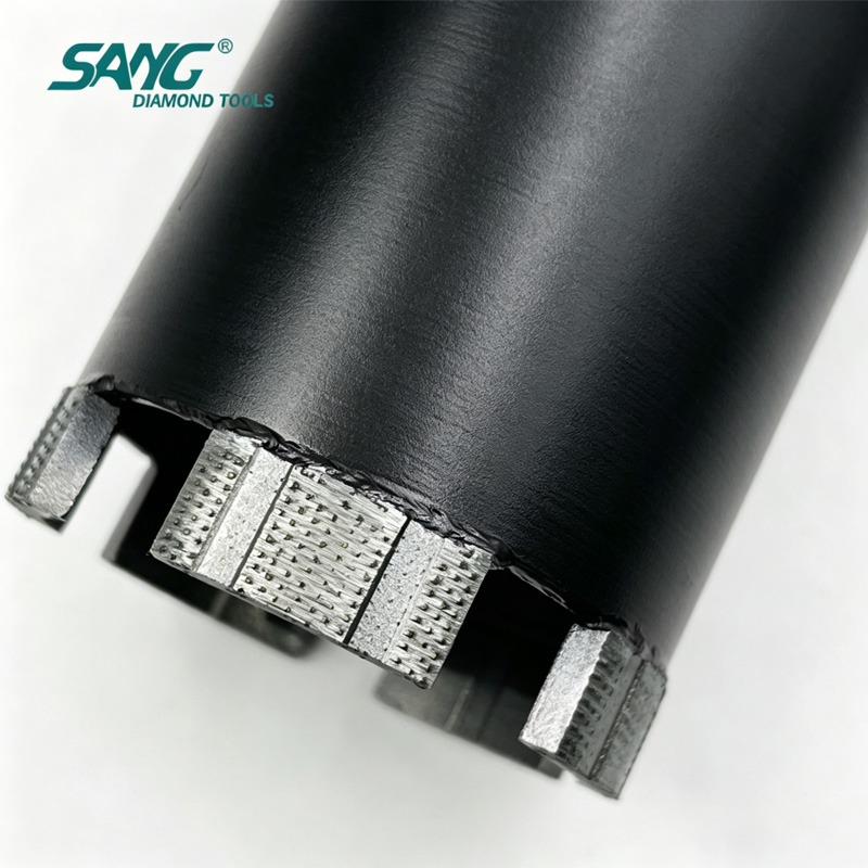
Quick Answer Yes — but only if you choose the right bit. A standard sintered core bit can cut reinforced concrete, but it dulls quickly on rebar, overheats in dry conditions, and loses segment bond strength under continuous load. A Laser Welded ARIX Technology Segment Diamond Core Drill Bitsolves all three problems simultaneously:
ARIX 3D segment geometry locks diamond particles in a three-dimensional matrix, exposing fresh cutting surfaces continuously instead of wearing flat.
Laser welding at 1,300–1,500 °C fuses the segment directly to the steel barrel — no braze alloy filler, no heat-damaged diamonds, no segment drop-off under vibration.
Dual wet/dry compatibility means the same bit works on a water-cooled rig for deep structural walls and a handheld dry drill for tight interior spaces.
If your project involves C30–C60 reinforced concrete with embedded rebar, this guide will help you spec the right bit, avoid the three most common procurement mistakes, and understand why bond type is more important than price per unit.
1. Why Reinforced Concrete Is a Different Problem
Reinforced concrete combines two materials with opposite wear characteristics:
Material
Hardness (Mohs)
Effect on Diamond Bit
Cured concrete (C40)
6–7
Abrasive — wears bond matrix
Steel rebar (Grade 60)
5–6
Impact-resistant — dulls diamond grit
Aggregate (quartz/granite)
6.5–7
High abrasion — accelerates segment wear
A bit optimized for concrete alone uses a hard bond to survive abrasion — but a hard bond glazes on rebar, causing the bit to skid rather than cut. A soft bond cuts rebar easily but wears out 30–50% faster in high-aggregate concrete.
ARIX technology resolves this trade-off by changing the geometry of the diamond distribution, not just the bond hardness.
2. What ARIX Technology Actually Means (And What It Does Not) ARIX is a patented three-dimensional segment architecture developed for high-performance diamond tooling. It is not a brand of diamond grit or a coating — it is a structural design for how synthetic diamond particles are arranged within the metal bond matrix.
Standard Segment vs. ARIX Segment
Feature
Standard Flat Segment
ARIX 3D Turbo Segment
Diamond distribution
Single horizontal layer
Multi-layer 3D matrix
Wear pattern
Uniform flat surface → polishing
Progressive exposure of fresh diamond
Self-sharpening
Low — requires dressing stone
High — auto-exposes new cutting edges
Cutting efficiency at depth
Decreases significantly after 50mm
Remains consistent to full barrel depth
Heat generation
Higher — flat surface creates friction zone
Lower — 3D profile improves chip evacuation
Rebar crossing
Segment may glaze
Turbo geometry maintains bite through steel
The turbo profile of an ARIX segment creates micro-channels between raised diamond ridges. These channels clear swarf and concrete dust during rotation, reducing friction heat by an estimated 15–25% compared to a flat segment under equivalent load. For procurement managers: this directly translates to fewer bit changes per shift and measurable reduction in downtime cost.
3. Why Laser Welding Matters More Than You Think Most diamond core bits in the mid-price range use high-frequency sintering or silver-braze bonding to attach segments to the steel barrel. Both methods work — until conditions get demanding.
Laser welding does not use a filler alloy. The laser melts a micro-zone of both the segment base and the barrel steel simultaneously, creating a molecular-level fusion bond. The result:
Segment shear strength is 40–60% higher than brazed bonds under lateral stress
No braze alloy layer to crack under thermal cycling (wet/dry switching)
Safe for use with high-torque hydraulic drilling rigs without segment detachment risk
At SANG Diamond Tools, our laser welding process is calibrated at our Quanzhou facility using automated laser parameters set by our PhD R&D team. Every barrel undergoes post-weld pull-test inspection before shipment.
4. Dry vs. Wet Cutting: When to Use Which Mode One of the most common procurement questions we receive: "Do I need to order separate bits for dry and wet drilling rigs?"
With a standard bit — yes. With a properly designed ARIX laser welded bit — no.
Wet vs. Dry Mode Decision Guide
Factor
Wet Drilling
Dry Drilling
Bit cooling
Water coolant via centre flush
Air + segment geometry
Dust control
Excellent — slurry contains dust
Requires dust shroud or extractor
Drilling speed
Higher — less heat buildup
Slightly slower; limited to shorter runs
Interior use
Messy — water management needed
Clean — preferred for occupied buildings
Rebar depth
Ideal for deep walls (>300mm)
Suitable to ~200mm in most configurations
Bit wear
Slower — water lubricates diamond contact
Faster if run too long without pause
SANG ARIX bit compatibility
Full — centre water flush compatible
Full — turbo channels provide air cooling
Practical rule: Use wet mode for structural drilling in walls, slabs, and foundations deeper than 200mm. Switch to dry mode for MEP rough-in, anchor bolt installations, and any work in occupied or finished interior spaces.
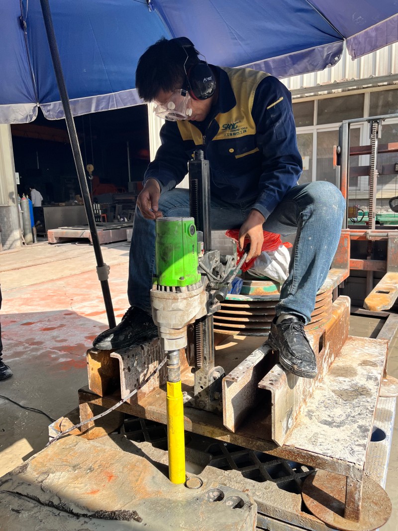
5. Real Project Case: High-Rise MEP Core Drilling, United States Project type: 42-story residential tower, mechanical/electrical/plumbing rough-in Material: C45 reinforced concrete shear walls, rebar density ~18 kg/m³ Requirement: 200 core holes of 82mm diameter through 300mm walls, 4-week schedule Tool used: SANG 82mm Laser Welded ARIX Core Bit, wet mode, hydraulic rig Results observed by the site contractor:
Average holes drilled per bit before segment wear: 210 holes (vs. 130–150 with competitor sintered bits previously used)
No segment detachment across entire run
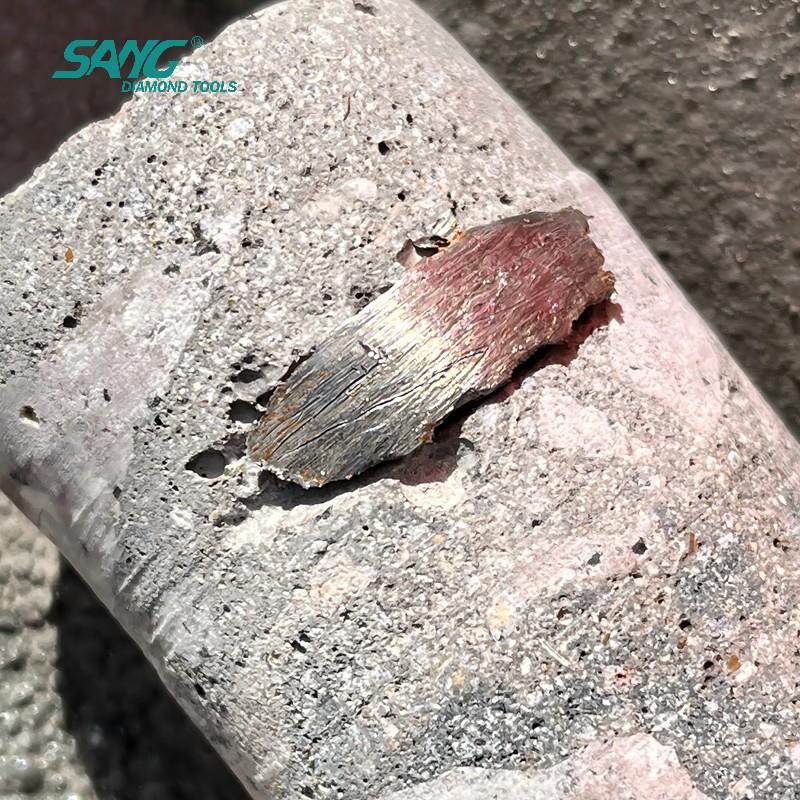
Core extraction clean — no spalling at hole perimeter
Schedule completed 3 days ahead of target due to reduced bit change downtime
Note: Results are reported by the contractor team. Performance varies by concrete grade, rebar density, equipment power, and operator technique.
Why this matters for procurement: At 210 holes per bit vs. 150, a project requiring 1,000 holes needs 4.8 SANG bits vs. 6.7 competitor bits. At a realistic per-bit price difference of 15–20%, the SANG option delivers lower total cost per hole — not just lower per-bit cost.
6. Procurement Checklist: 8 Specifications to Confirm Before Ordering If you are a procurement manager, distributor, or project engineer ordering ARIX core bits for reinforced concrete work, confirm these eight parameters before placing an order:
Diameter — Match to the nominal hole size required (add 2–3mm for clearance fit on conduit/pipe)
Barrel length — Must exceed wall/slab thickness; standard lengths are 300mm, 450mm, 600mm
Connection thread — 1-1/4" UNC (most hydraulic rigs), M16, R½", or SDS adapter available
Wet / dry designation — Confirm centre flush port for wet mode; blank end cap for dry mode
Concrete grade — C30–C50: medium bond; C50–C60: soft-medium bond for ARIX geometry to self-sharpen
Rebar density — Heavy rebar (>20 kg/m³): specify laser welded; avoid brazed bits
Segment height — Standard 10mm for general use; 12mm for extended-run projects
Certification — Confirm ISO 9001 and any required market certifications (CE for EU, etc.)
SANG Diamond Tools provides technical specification sheets for all standard ARIX core bit configurations. Custom diameters from 14mm to 426mm are available with a minimum lead time of 7 working days.
7. How SANG Designs ARIX Core Bits: The Engineering Perspective SANG Diamond Tools was established in 1993 in Quanzhou, Fujian — a region with a 30+ year manufacturing heritage in diamond tooling. We are recognized as a Top 10 Manufacturer in China's diamond tool industry, supplying distributors and contractors in 75+ countries including the United States, Germany, Australia, Italy, and Poland. Our ARIX core bit development process: Step 1 — Bond formula design Our R&D center, led by PhD researchers with backgrounds in materials science and powder metallurgy, designs bond matrices at the molecular level. Bond hardness is calibrated to match expected concrete grade ranges rather than applying a one-size formula.
Step 2 — Diamond selection and layer mapping Synthetic diamond grit is sorted by crystal shape and strength. The ARIX 3D layout places primary cutting diamonds at the segment crown and secondary diamonds in the mid-layer to activate as the primary layer wears.
Step 3 — Hot press sintering Diamond-metal powder mixes are sintered under controlled temperature and pressure. Parameters are logged per batch for quality traceability.
Step 4 — Laser weld attachment Segments are laser welded to the barrel steel in an automated fixture. Weld parameters are set per segment geometry and barrel wall thickness.
Step 5 — Post-weld inspection Each bit undergoes dimensional inspection, runout check (< 0.3mm TIR), and segment pull-test before packing.
This five-step process is why our ARIX bits consistently outperform imported alternatives in independent contractor field tests — and why we can offer container-load supply without quality variance between batches.
8. Core Key Takeaways Before you close this page, here is what matters most:
Reinforced concrete drilling requires a bit engineered for both abrasive concrete and impact-resistant rebar — standard bits are not designed for both simultaneously.
ARIX 3D segment geometry continuously exposes fresh diamond, maintaining consistent cut speed and reducing the glazing problem common with flat segments on rebar.
Laser welding at 1,300–1,500 °C creates a direct steel fusion bond — the segment cannot detach under the vibration and torque of hydraulic drilling rigs.
Dual wet/dry capability means one SKU covers both hydraulic wet rigs and handheld dry drills, simplifying procurement and reducing warehouse SKU count.
Total cost per hole — not unit price — is the correct metric for evaluating core bit procurement. More holes per bit = lower cost per hole even at a higher per-unit price.
SANG Diamond Tools has supplied ARIX core bits to contractors in 75+ countries since 1993, with full technical support from a PhD-led R&D team and certified quality management under ISO 9001.
9. FAQ
Q1: What is the difference between an ARIX core bit and a standard turbo core bit? A standard turbo bit has a shaped rim but uses a single-layer diamond distribution. An ARIX bit uses a three-dimensional multi-layer matrix where diamonds are positioned at different depths within the segment. As the outer layer wears, the next layer activates — this is what makes ARIX self-sharpening rather than self-dulling.
Q2: Can I use a laser welded ARIX bit on a standard handheld drill? Yes, provided the drill has sufficient torque (typically ≥900W for bits up to 82mm diameter) and you use the correct adaptor. For dry handheld drilling, keep individual runs under 30 seconds and allow the bit to cool between holes. For sustained drilling, a rig-mounted setup with water flush is recommended.
Q3: What concrete grades are SANG ARIX core bits rated for? Our standard ARIX range is designed for C30–C60 reinforced concrete. For ultra-high-strength concrete (C60+) or concrete with aggregate harder than 7 Mohs, contact our technical team for a custom bond specification.
Q4: How do I know if my current core bit glazing problem is a bond issue or a technique issue? If the bit cuts well for the first 10–15 holes then progressively slows, it is likely a bond-glazing issue (bond too hard for the concrete). If it cuts slowly from the first hole, it may be an RPM or water flow issue. SANG's technical team offers free remote video consultation to diagnose field problems.
Q5: What is the minimum order quantity for SANG ARIX core bits? Standard configurations are available from 1 piece for sample/trial orders. Container-load pricing is available for distributors. Custom diameter or thread specifications require a minimum of 10 pieces per SKU. Lead time: 5–7 working days for stock configurations, 10–15 days for custom.
Q6: Do SANG ARIX core bits come with CE or other certifications? Yes. SANG Diamond Tools holds ISO 9001 quality certification. Our diamond saw blades and grinding tools carry applicable international certifications. Specific certification documentation can be provided upon request for procurement or import compliance purposes.
Q7: What technical support does SANG provide after the sale? Our technical engineers provide online video consultations for bit selection, machine calibration, and troubleshooting. Offline on-site support is available for large project orders. Our sales team includes TEM-8 English graduates and staff fluent in French, Spanish, Persian, and other languages.
10. Ready to Spec Your Next Core Bit Order? If you are a contractor, distributor, or procurement manager sourcing ARIX core bits for reinforced concrete projects, SANG Diamond Tools offers:
Free technical consultation — describe your concrete grade, rebar density, wall thickness, and drilling rig; we will recommend the right specification
Trial sample orders — test performance on your job site before committing to project volumes
Custom diameter and thread configurations — 14mm to 426mm, all standard thread connections
Container-load supply — 50+ workshop staff, automated production lines, consistent quality across batches
Contact: info@sangtools.com | www.sangtools.com
SANG Diamond Tools — Established 1993 | Quanzhou, Fujian, China | Exporting to 75+ Countries Top 10 Diamond Tool Manufacturer in China | ISO 9001 Certified | PhD-Led R&D Team
Best Laser Welded ARIX Diamond Core Drill Bit for Reinforced Concrete | SANG Diamond Tools
Discover how laser welded ARIX diamond core drill bits improve drilling speed, lifespan, and safety in reinforced concrete. Learn how to choose the right core bit from SANG — 30+ years of manufacturing expertise, trusted in 75+ countries.
What Is the Best Laser Welded ARIX Diamond Core Drill Bit for Reinforced Concrete? A Complete Buyer's Guide By SANG Diamond Tools Technical Team | Est. 1993 | Top 10 Manufacturer in China | Trusted in 75+ Countries
Quick Answer If you're a procurement manager, contractor, or distributor evaluating core drill bits for reinforced concrete, here's what you need to know upfront:
Selection Criteria
Recommended Answer
Best segment technology
ARIX array-pattern diamond distribution
Best bonding method
Laser welding (not silver brazing)
Dry or wet cutting?
Both — dual-rated bits available
Can it drill through rebar?
Yes — ARIX maintains stable cutting through steel reinforcement
Bottom line:For reinforced concrete with rebar, a laser-welded ARIX segment core bit is not a premium upgrade — it is the baseline requirement for professional, safe, and cost-effective drilling.
Why Reinforced Concrete Is the Ultimate Test for Any Core Drill Bit Reinforced concrete is not a uniform material. It is an engineered composite of high-strength cement matrix, hard aggregate, and embedded steel reinforcement — and each element attacks your drill bit differently.
The Six Failure Modes in Reinforced Concrete Drilling
Failure Mode
Root Cause
Impact on Project
Segment glazing
Bond too hard for concrete hardness
Drilling stops entirely — must re-dress or replace
Rebar impact fracture
Silver-brazed bond cannot absorb shock
Segment detachment — safety incident
Thermal delamination
Heat exceeds brazed joint tolerance (~650°C)
Segment loss mid-hole — borehole damage
Bit vibration / drift
Uneven segment wear, unbalanced cutting
Hole deviation — structural non-compliance
Premature diamond burial
Random distribution leaves inactive zones
Slow drilling, high cost per hole
Core barrel warping
Thin-wall barrel under continuous rebar impact
Bit seizure in borehole — extraction cost
Standard silver-brazed bits with random diamond distribution are not engineered to handle this combination of failure modes simultaneously. ARIX technology and laser welding address each one at a fundamental manufacturing level.
What Is ARIX Technology? The Engineering Behind the Performance ARIX (Array Pattern) technology is a diamond placement methodology that positions individual diamond crystals in a precise, repeating three-dimensional geometric matrix within the metal bond segment — rather than the random distribution used in conventional segments.
Random vs. ARIX: A Side-by-Side Comparison
Performance Factor
Conventional Random Segment
ARIX Array Pattern Segment
Diamond placement
Irregular, clustered in zones
Precise geometric array, uniform spacing
Active cutting diamonds per pass
Variable — depends on which diamonds surface
Consistent — geometry guarantees exposure
Drilling speed
Medium, inconsistent
High, stable throughout tool life
Segment wear pattern
Uneven — causes vibration and drift
Uniform — maintains rotational balance
Rebar performance
Speed drops sharply at steel contact
Stable cutting rhythm maintained
Heat management
Localized hotspots at diamond clusters
Distributed — no single thermal concentration point
Tool lifespan vs. standard
Baseline
30–50% longer
Cost per hole drilled
Higher
Significantly lower
Hole wall quality
Standard roughness
Smoother bore wall
Why geometry matters at the microscopic level: Each diamond crystal in an ARIX segment has a defined neighborhood of bond matrix around it. When the segment contacts rebar, the impact load is distributed across multiple crystals simultaneously — no single crystal absorbs full shock. This is the physical reason ARIX bits survive rebar contact that destroys conventional segments.
SANG Engineering Note: SANG's PhD research team developed the ARIX matrix spacing specifically calibrated for the concrete density ranges and rebar configurations specified in ACI 318 (North America) and Eurocode 2 (Europe). The bond formulation is not adapted from a generic catalog — it is application-engineered for the markets where our customers operate.
Product Specifications: SANG Laser-Welded ARIX Core Drill Bit
Specification
Standard Options
Custom Available
Segment technology
ARIX array pattern, premium industrial diamond
Custom diamond grade on request
Welding method
High-precision laser welding
—
Cutting mode
Dry & Wet (dual-rated)
—
Diameter range
14mm – 300mm
Beyond 300mm on request
Connection types
1/2" Gas (BSP), 5/8"-18 UNC, 1-1/4" UNC, SDS-Max, SDS-Plus, M22
Non-standard threads on request
Barrel lengths
300mm / 400mm / 450mm / 500mm/ 600mm
Extended lengths on request
Segment height
10mm / 11mm / 12mm
Application-matched on request
Bond hardness
Soft / Medium / Hard
Custom formulation for specific concrete grades
Target material
Reinforced concrete, rebar-dense structures, hard aggregate
—
Certifications
ISO 9001, CE, National Industry Patents (CN)
—
OEM / Private label
Available
Contact SANG sales team
Selecting the Right Specification: A Step-by-Step Framework Step 1 — Define Your Hole Diameter
Diameter
Typical Application
32mm
Plumbing pipe penetrations, anchor bolts
52mm
Electrical conduit, small HVAC penetrations
82mm
Medium HVAC, structural anchor drilling
102mm
Large conduit, utility penetrations
152mm
Major HVAC, significant structural openings
202mm+
Infrastructure, bridge deck penetrations
Step 2 — Define Your Concrete Specification
Concrete Grade
Recommended Bond
C20–C30 (residential)
Hard bond segment
C30–C40 (commercial)
Medium bond segment
C40–C50 (industrial / infrastructure)
Soft-medium bond, ARIX reinforced
C50+ (bridge / tunnel)
Contact SANG engineering for custom bond formulation
Step 3 — Define Your Drilling Mode
Mode
When to Choose
Key Requirements
Dry
No water access, indoor renovation, electrical rooms
Maximum tool life, high rebar density, C40+ concrete
Clean water at 2–4 L/min; flush every 150mm
Dual-rated
Mixed job site conditions
SANG standard ARIX specification
Step 4 — Match Your Connection and Equipment
Connection Type
Compatible Equipment
1/2" Gas (BSP)
Core drilling rigs, wall saws
1-1/4" UNC
North American rig-mounted systems
SDS-Max
Professional rotary hammer drills (≥ 5kg class)
SDS-Plus
Medium-duty rotary hammers
M22
European handheld core drills
Dry Cutting vs. Wet Cutting: Operational Guide
Dry Cutting Best for: Indoor renovation, upper floors, confined spaces, electrical rooms, data centers, post-tensioned slabs where water is prohibited.
Operational requirements: 1.Vacuum dust extraction is mandatory — silica dust regulations apply globally (OSHA 29 CFR 1926.1153 / EU Directive 2017/164) 2.Apply thermal rest intervals: 30 seconds cutting, 10 seconds retraction for airflow cooling 3.Do not exceed the diameter-rated maximum RPM — dry heat accumulates significantly faster than wet Performance expectation: 10–20% shorter tool life vs. wet cutting in identical concrete. Acceptable when water access is not available.
Wet Cutting Best for: Maximum tool life per unit, high rebar density (3+ bars per borehole), consecutive large-diameter holes (>100mm), C40+ concrete.
Operational requirements: 1.Maintain continuous water flow at 2–4 L/min throughout drilling 2.Use clean water supply — recirculated contaminated slurry accelerates segment wear by up to 40% 3.Flush borehole every 150mm depth to clear accumulated swarf and prevent bit seizure
Real Application Case: Infrastructure Bridge Deck Drilling
"We were replacing bits every half day. After switching to SANG ARIX bits, we finished the full 180-hole program with 7 bits and zero safety incidents. The consistency through the rebar grid was unlike anything we had used before." — Project Manager, Bridge Infrastructure Contractor
Why SANG: Supplier Evaluation for Procurement Managers For procurement managers and distributors, tool performance is only part of the supplier evaluation. Supply reliability, technical capability, and communication quality determine whether a supplier relationship can scale to meet project demands.
SANG vs. Generic Suppliers: Complete Evaluation Matrix
75+ countries — US, EU, AU, Middle East, Latin America
Language capability
Basic
English only TEM-8 English + French, Spanish, Persian & more
Technical support
Email only
Video consultation + on-site engineering
OEM / Custom capability
Rarely available
Full OEM/ODM, custom bond formulation
Sample availability
Inconsistent
1–10 pcs sample orders supported
Batch consistency
Unverified
ISO 9001 governed, CoC available per batch
Frequently Asked Questions
Q1: Can this bit drill through rebar without stopping?
Yes. ARIX technology is specifically designed to maintain stable cutting performance at the concrete-to-rebar transition. Unlike standard bits that lose speed or skip at rebar contact, ARIX geometric diamond placement distributes impact across multiple crystals, allowing continuous penetration.
Q2: Is laser welding actually stronger than silver brazing in practice?
Yes — measurably so. Laser welding produces a molecular fusion bond with tensile strength of 3,500–5,000 N, compared to 1,200–1,800 N for silver brazing. More importantly, laser welds maintain structural integrity at temperatures up to 900°C, which is critical during dry cutting or sustained rebar contact. Silver-brazed joints fail at approximately 650°C — well within the temperature range generated during normal reinforced concrete drilling.
Q3: What is the minimum order quantity for SANG ARIX core bits?
SANG supports sample orders of 1–10 pcs for field testing and evaluation, as well as full container-load bulk orders. Lead times are confirmed at order placement. Contact info@sangtools.com for formal quotation and sample arrangements.
Q4: Can SANG produce custom diameters or non-standard connection types?
Yes. With 31 years of OEM/ODM experience, SANG routinely produces custom specifications including non-catalog diameters, extended barrel lengths, and proprietary connection threads. Standard lead time for custom tooling is 15–25 working days depending on complexity.
Q5: How is batch-to-batch quality consistency guaranteed for large orders?
All production runs are governed by SANG's ISO 9001 Quality Management System. Each batch undergoes segment height verification, bond hardness testing, and laser weld integrity inspection before shipment. Certificate of Conformity is issued on request for each production batch.
Q6: How do I select the right bond hardness for my specific concrete?
Provide your concrete grade (MPa or PSI rating), aggregate type and maximum size, rebar density and diameter, and drilling machine power rating. SANG's technical team will issue a formal tooling recommendation — free of charge as a standard pre-order technical service.
Q7: How should diamond core bits be maintained to maximize service life?
Key maintenance practices: avoid excessive downward drilling pressure; maintain continuous water supply during wet cutting; allow thermal rest cycles during dry cutting; dress glazed segments promptly on a concrete block or dressing stick; store bits vertically in a dry environment; never use a bit rated below your machine's maximum RPM.
Q8: Does SANG support OEM / private label for distributors?
Yes. Full OEM service including custom packaging design, private label branding, and distributor-exclusive specifications is available. Minimum order quantities apply — contact the SANG sales team for a confidential OEM discussion.
Contact SANG Diamond Tools www.sangtools.com | info@sangtools.com Est. 1993 | Top 10 China Diamond Tool Manufacturer | 75+ Countries | ISO 9001 | CE Certified