Whether you're embarking on a DIY tile installation project or a professional contractor in need of reliable tools, selecting the right tile cutter is crucial. With a wide range of options available in the market, it can be overwhelming to find the perfect tool that meets your specific needs. this guide, we will explore the key factors to consider when choosing a tile cutter. By the end, you'll be equipped with the knowledge to make an informed decision and find a tile cutter that fits your requirements.
1. Types of Tile Cutters:
There are various types of tile cutters available, each suitable for specific tile materials and cutting applications. The three main types include:
a. Manual Tile Cutters: These are affordable and portable options for cutting ceramic and porcelain tiles. They feature a scoring mechanism and a snapping action for straight cuts.
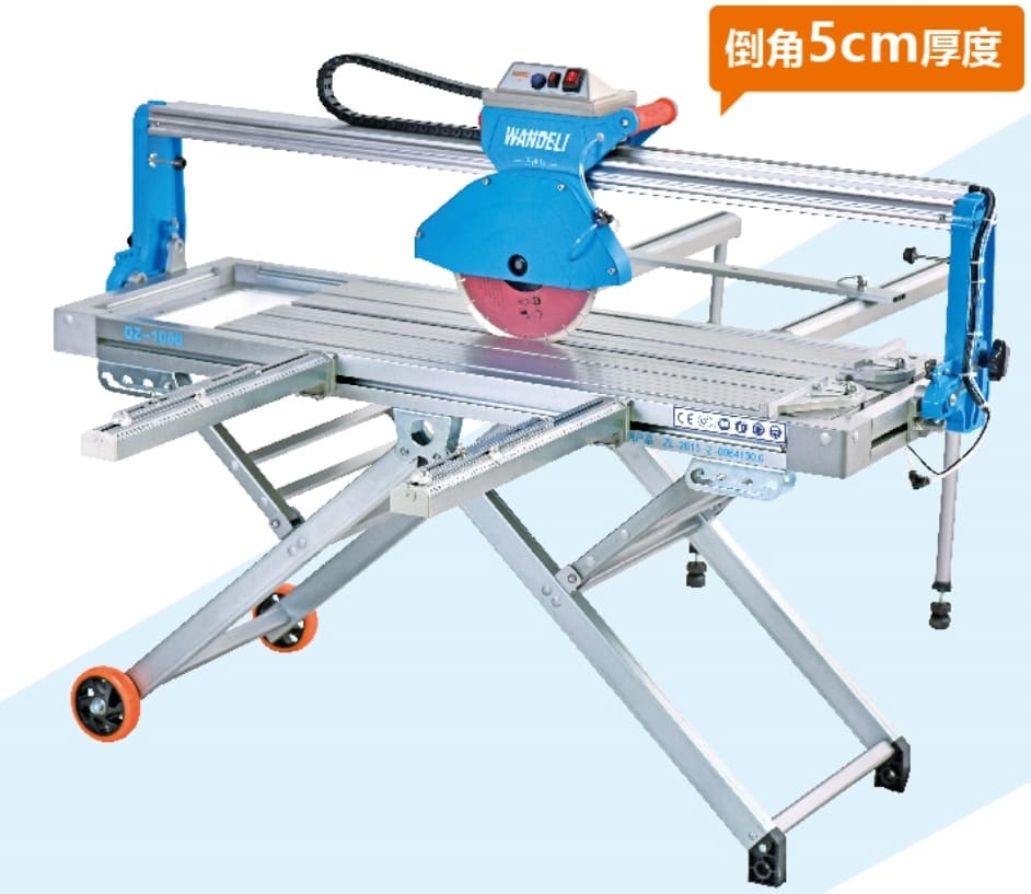
b. Wet Tile Saws: Ideal for cutting through tougher materials like stone and thicker tiles, wet tile saws use a diamond-coated blade and water to create precise and clean cuts.
c. Tile Nippers and Mosaic Cutters: These hand-held tools are designed for more intricate or curved cuts, typically used for mosaic tiles or irregular-shaped pieces.
2. Consider the Tile Material and Size:
Different tile materials require specific cutting methods and tools. Consider whether you'll be working with ceramic, porcelain, stone, or glass tiles, as this will affect the type of cutter you'll need. Additionally, assess the size and thickness of the tiles you'll be cutting to ensure the chosen cutter can handle them effectively.
3. Cutting Capacity and Blade Quality:
Evaluate the cutting capacity of the tile cutter, including the maximum size and thickness it can accommodate. Look for a cutter with a sturdy and durable blade, preferably made of high-quality materials like tungsten carbide or diamond-coated for superior cutting performance and longevity.
4. Ease of Use and Accuracy:
Look for a tile cutter that offers ease of use and ensures accurate cuts. Features like adjustable guides, clear cutting lines, and smooth gliding mechanisms contribute to a more user-friendly experience and precise results. Some tile cutters may even have laser guides or built-in measurement systems for added accuracy.
5. Portability and Stability:
Consider your workspace and whether you'll need to transport the tile cutter. If portability is important, opt for a lightweight and foldable model. However, ensure it still provides stability during operation to prevent inaccuracies or accidents.
6. Safety Features:
Prioritize safety by choosing a tile cutter with adequate safety features. Look for models with blade guards, non-slip bases, and ergonomic handles that minimize the risk of injury during use.
7. Budget and Long-Term Investment:
Set a budget based on your requirements and the scale of your tiling projects. While it's essential to find an affordable option, don't compromise on quality. Consider the long-term investment value of the tile cutter, as a higher-quality tool may provide better durability and performance, ultimately saving you time and money in the long run.
Conclusion:
Choosing the right tile cutter is essential for achieving accurate and clean cuts, whether you're a DIY enthusiast or a professional contractor. Consider the tile material, cutting capacity, ease of use, portability, safety features, and budget when making your decision. By carefully assessing these factors, you'll find a tile cutter that meets your needs and ensures successful tile installations every time. Happy cutting!