头部背景图片

What's the Secret to Versatile, Cost-Effective Cooling

2025-05-15

Among the many pieces of equipment in industrial settings, dual-mode screw inverter chillers shine like unique gems, offering exceptional value. For businesses, understanding their special features not only maximizes their efficiency but also brings unexpected benefits in cost control and productivity improvement. Whether in the production workshops of large factories or the server rooms of data centers, dual-mode screw inverter chillers play a vital role. Today, let’s explore what makes them so special.


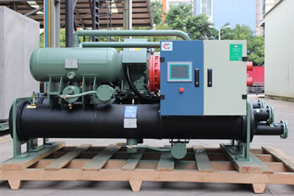
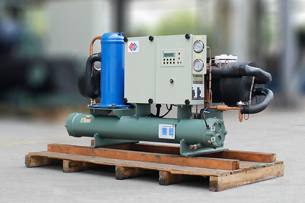
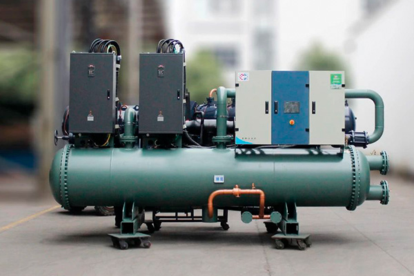
Hstars Energy Efficiency Screw Inverter Chiller


1. Dual-Mode Operation

One of the standout features of dual-mode screw inverter chillers is their ability to operate in two distinct modes: cooling and ice-making. They can seamlessly switch between these modes based on actual needs. In cooling mode, they provide a stable low-temperature environment for production equipment and office spaces, effectively reducing temperatures and ensuring smooth operations while preventing overheating-related failures or reduced lifespan. In ice-making mode, they meet the demands of specialized processes, such as rapid ice production in food processing or ice storage for cooling in buildings during off-peak hours, releasing stored cooling during peak hours to save on electricity costs.

2. Advantages of Screw Inverter Technology

Another key feature is the use of screw inverter technology. Screw compressors are known for their compact structure and high efficiency, and the addition of inverter functionality takes their performance to the next level. The chiller can automatically adjust the compressor speed based on actual cooling load demands, eliminating the frequent start-stop issues of traditional fixed-speed chillers. During low-load operation, the inverter chiller reduces energy consumption and minimizes waste. For businesses, this translates to significant long-term cost savings and aligns with modern sustainability goals by reducing energy consumption and emissions.


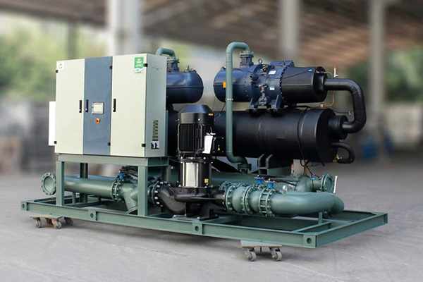
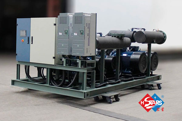
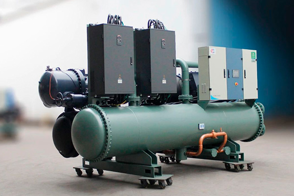
Hstars Precise Temperature Control Industrial Chiller


3. Precise Temperature Control

Dual-mode screw inverter chillers excel in temperature control, maintaining precise temperatures within a narrow range. This is crucial for industries with stringent temperature requirements, such as electronic chip manufacturing or precision instrument processing. Accurate temperature control ensures consistent product quality, reduces defect rates caused by temperature fluctuations, and enhances overall production efficiency.

4. Wide Applicability

These chillers are highly versatile, suitable for both small and large enterprises across industrial and commercial sectors. In industrial applications, they are used for temperature regulation in industries like chemicals, pharmaceuticals, and textiles. In commercial settings, they provide cooling for air conditioning systems in malls, hotels, and other spaces, meeting diverse cooling needs across different areas and time periods.
With their dual-mode operation, screw inverter technology, precise temperature control, and wide applicability, dual-mode screw inverter chillers hold an irreplaceable position in industrial and commercial settings. They act as reliable assistants, safeguarding production and operations while improving efficiency, reducing costs, and ensuring product quality. When considering cooling equipment, dual-mode screw inverter chillers are undoubtedly a top-tier choice worth exploring.


How to improve the quality of solar cells

2025-05-13

In today's world that relies on clean energy, the efficiency and reliability of solar cells are of vital importance. As a company specializing in providing mechanical testing equipment, we have specialized equipment for tensile testing of battery cell welding strips. This product will assist manufacturers and testing laboratories in enhancing the quality control of solar cells and ensuring their stability in harsh environments.


Understand the importance of welding strip stretching:

The welding strips of solar cells play a crucial connecting role in the battery modules. The quality of the welding tape directly affects the performance and lifespan of the battery. Therefore, solar cell manufacturers and testing laboratories need a reliable testing device to evaluate the tensile properties of the welding strips. Our solar cell welding strip tensile testing machine can provide accurate and repeatable test results, helping you determine the connection quality between the welding strip and the cell, thereby enhancing the overall reliability and performance of the product.


Outstanding functionality and innovative design:

Our solar cell welding strip tensile testing machine features a series of outstanding functions and innovative designs, making it one of the most advanced devices on the market. The following are some prominent features:

  1. Precise mechanical measurement: Our machine adopts advanced mechanical sensing technology, which can accurately measure the force and displacement of the welding strip during the stretching process. This ensures that you obtain accurate test results and helps you evaluate the material properties of the welding tape.
  2. Multi-functional test modes: Our machine features multiple test modes, including static tensile, cyclic tensile, and breaking strength tests. This means that you can conduct comprehensive tests and evaluations of the welding strips according to different needs to ensure their stability and reliability under various stress conditions.
  3. Intuitive user interface: Our machines are equipped with an intuitive user interface, making operation simple and easy to understand. You can easily set test parameters, monitor the test process, and obtain data and results in real time. This makes the testing process efficient and easy to operate.


The advantages of focusing on performance:

  1. Reliability and accuracy: Our machines have been meticulously designed and tested to ensure they possess a high level of reliability and measurement accuracy. You can trust our equipment to provide you with accurate test results.
  2. High efficiency and time-saving: Our machines feature high testing speed and rapid data processing capabilities, helping you save time and resources. You can focus more on other core businesses and improve production efficiency.
  3. Customization and Support: We offer customized solutions to meet the specific needs of different customers. In addition, we also offer comprehensive after-sales support and maintenance services to ensure that you can make full use of our equipment.


If you are a decision-maker in a solar cell manufacturer or testing laboratory, we strongly recommend that you choose our solar cell solder strip tensile testing machine. It will provide you with accurate and reliable test results and help you improve the quality and reliability of solar cells. Please contact us immediately to learn more about our products and solutions. Let's work together to jointly promote the development of clean energy technologies!

The necessity of high-flexibility cable bending equipment

2025-05-13

From surgical robots' precise movements to EV charging piles' high-power transmission, high-flex cables act as the "lifeline" of modern equipment. Yet according to the Global Cable Reliability Report 2024bending fatigue-induced cable failures cost manufacturers over $1.7 billion annually. How to guarantee long-term reliability under complex motions? Tophung delivers the definitive solution.


Analysis of Industry Pain Points

The three fatal flaws of the current industry:

False safety certification: Laboratory one-way bending test vs. Multi-angle twisting in Real scenarios

Inefficient verification system: Traditional equipment tests only one cable at a time and it takes 20 days to complete 100,000 cycles

Hidden damage out of control: Manual detection fails to identify the initial microcracks (< 50μm), resulting in sudden fracture


Solution:

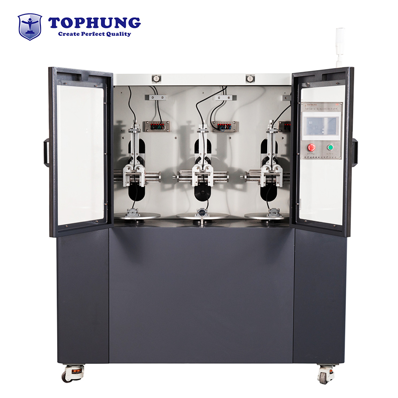
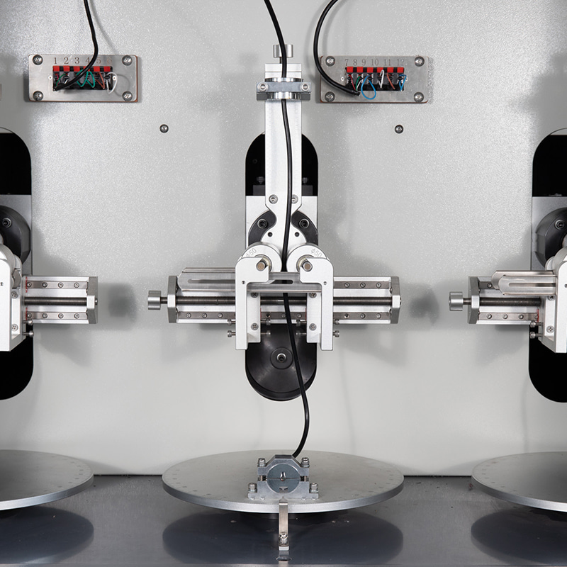
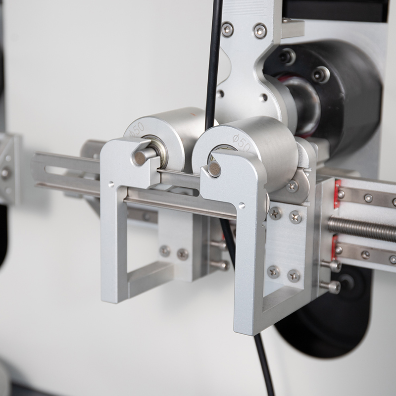
The Tophung wire and Cable 3D torsion testing machine is suitable for the testing requirements of high-flexibility cables such as TUV, VDE, and UL. The Cable 3D torsion testing machine structure is a composite torsion - bending and torsion combined synchronous test structure, simulating the operation scene of a mechanical arm to achieve multi-angle torsion tests.

  • #
  • #
  • #

Core advantage

  • Reproduction of real working conditions:

Simulate the operation scene of the mechanical arm and support custom programming for bending angles and torsion angles

  • Ultra-large-scale parallel testing:

Exclusive 3-channel design enables simultaneous testing of 3 groups of cables at a time, saving testing time

  • Extreme environment simulation:

An optional temperature control chamber with a temperature range of -40 to 100 is available to verify the performance attenuation of the cable under extremely cold or high heat conditions


Technical Specs

Bending radius range: 10mm to 75mm (adjustable)

Torsion Angle: 0° to ±120° (adjustable)

The test speed is 0 to 60 times per minute

The sample diameter ranges from Ф1.0mm to Ф16mm


Our wire and cable bending fatigue testing machine adopts leading mechanical testing technology and features high precision and reliability. It not only has standard testing functions, but also supports customized testing solutions to meet various needs. Choose our Cable 3D torsion testing machine and you will achieve the perfect combination of technological leadership, cost-effectiveness and customer satisfaction.


A Brief Discussion on the Use and Maintenance of Environmental Testing Chamber

2025-05-12

Ⅰ. Proper Use of LABCOMPANION's Instrument

Environmental testing equipment remains a type of precision and high-value instrument. Correct operation and usage not only provide accurate data for testing personnel but also ensure long-term normal operation and extend the equipment's service life.


First, before conducting environmental tests, it is essential to familiarize oneself with the performance of the test samples, test conditions, procedures, and techniques. A thorough understanding of the technical specifications and structure of the testing equipment—particularly the operation and functionality of the controller—is crucial. Carefully reading the equipment’s operation manual can prevent malfunctions caused by operational errors, which may lead to sample damage or inaccurate test data.


Second, select the appropriate testing equipment. To ensure smooth test execution, suitable equipment should be chosen based on the characteristics of the test samples. A reasonable ratio should be maintained between the sample volume and the effective chamber capacity of the test chamber. For heat-dissipating samples, the volume should not exceed one-tenth of the chamber’s effective capacity. For non-heating samples, the volume should not exceed one-fifth. For example, a 21-inch color TV undergoing temperature storage testing may fit well in a 1-cubic-meter chamber, but a larger chamber is required when the TV is powered on due to heat generation.


Third, position the test samples correctly. Samples should be placed at least 10 cm away from the chamber walls. Multiple samples should be arranged on the same plane as much as possible. The placement should not obstruct the air outlet or inlet, and sufficient space should be left around the temperature and humidity sensors to ensure accurate readings.


Fourth, for tests requiring additional media, the correct type must be added according to specifications. For instance, water used in humidity test chambers must meet specific requirements: the resistivity should not be less than 500 Ω·m. Tap water typically has a resistivity of 10–100 Ω·m, distilled water 100–10,000 Ω·m, and deionized water 10,000–100,000 Ω·m. Therefore, distilled or deionized water must be used for humidity tests, and it should be fresh, as water exposed to air absorbs carbon dioxide and dust, reducing its resistivity over time. Purified water available on the market is a cost-effective and convenient alternative.


Fifth, proper use of humidity test chambers. The wet-bulb gauze or paper used in humidity chambers must meet specific standards—not just any gauze can substitute. Since relative humidity readings are derived from the dry-bulb and wet-bulb temperature difference (strictly speaking, also influenced by atmospheric pressure and airflow), the wet-bulb temperature depends on water absorption and evaporation rates, which are directly affected by the gauze quality. Meteorological standards require that wet-bulb gauze must be a specialized "wet-bulb gauze" made of linen. Incorrect gauze may lead to inaccurate humidity control. Additionally, the gauze must be installed properly: 100 mm in length, tightly wrapped around the sensor probe, with the probe positioned 25–30 mm above the water cup, and the gauze immersed in water to ensure precise humidity control.


Ⅱ. Maintenance of Environmental Testing Equipment

Environmental testing equipment comes in various types, but the most commonly used are high-temperature, low-temperature, and humidity chambers. Recently, combined temperature-humidity test chambers integrating these functions have become popular. These are more complex to repair and serve as representative examples. Below, we discuss the structure, common malfunctions, and troubleshooting methods for temperature-humidity test chambers.


(1) Structure of Common Temperature-Humidity Test Chambers

In addition to proper operation, test personnel should understand the equipment’s structure. A temperature-humidity test chamber consists of a chamber body, air circulation system, refrigeration system, heating system, and humidity control system. The air circulation system typically features adjustable airflow direction. The humidification system may use boiler-based or surface evaporation methods. The cooling and dehumidification system employs an air-conditioning refrigeration cycle. The heating system may use electric fin heaters or direct resistance wire heating. Temperature and humidity measurement methods include dry-wet bulb testing or direct humidity sensors. Control and display interfaces may feature separate or combined temperature-humidity controllers.


(2) Common Malfunctions and Troubleshooting Methods for Temperature-Humidity Test Chambers

1.High-Temperature Test Issues


  • If the temperature fails to reach the set value, inspect the electrical system to identify faults.
  • If the temperature rises too slowly, check the air circulation system, ensuring the damper is properly adjusted and the fan motor is functioning.
  • If temperature overshooting occurs, recalibrate the PID settings.
  • If the temperature spikes uncontrollably, the controller may be faulty and require replacement.


2.Low-Temperature Test Issues


  • If the temperature drops too slowly or rebounds after reaching a certain point:

               Ensure the chamber is pre-dried before testing.

               Verify that samples are not overcrowded, obstructing airflow.

               If these factors are ruled out, the refrigeration system may need professional servicing.

  • Temperature rebound is often due to poor ambient conditions (e.g., insufficient clearance behind the chamber or high ambient temperature).


3.Humidity Test Issues


  • If humidity reaches 100% or significantly deviates from the target:


               For 100% humidity: Check if the wet-bulb gauze is dry. Inspect the water level in the wet-bulb sensor’s reservoir and the automatic water supply system. Replace or clean hardened gauze if necessary.


               For low humidity: Verify the humidification system’s water supply and boiler level. If these are normal, the electrical control system may require professional repair.


4.Emergency Faults During Operation


  • If the equipment malfunctions, the control panel will display an error code with an audible alarm. Operators can refer to the troubleshooting section in the manual to identify the issue and arrange for professional repairs to resume testing promptly.


Other environmental testing equipment may exhibit different issues, which should be analyzed and resolved case by case. Regular maintenance is essential, including cleaning the condenser, lubricating moving parts, and inspecting electrical controls. These measures are indispensable for ensuring equipment longevity and reliability.


Accelerated Environmental Testing Technology

2025-05-12

Traditional environmental testing is based on the simulation of real environmental conditions, known as environmental simulation testing. This method is characterized by simulating real environments and incorporating design margins to ensure the product passes the test. However, its drawbacks include low efficiency and significant resource consumption.


Accelerated Environmental Testing (AET) is an emerging reliability testing technology. This approach breaks away from traditional reliability testing methods by introducing a stimulation mechanism, which significantly reduces testing time, improves efficiency, and lowers testing costs. The research and application of AET hold substantial practical significance for the advancement of reliability engineering.


Accelerated Environmental Testing

Stimulation testing involves applying stress and rapidly detecting environmental conditions to eliminate potential defects in products. The stresses applied in these tests do not simulate real environments but are instead aimed at maximizing stimulation efficiency.


Accelerated Environmental Testing is a form of stimulation testing that employs intensified stress conditions to assess product reliability. The level of acceleration in such tests is typically represented by an acceleration factor, defined as the ratio of a device's lifespan under natural operating conditions to its lifespan under accelerated conditions.


The stresses applied can include temperature, vibration, pressure, humidity (referred to as the "four comprehensive stresses"), and other factors. Combinations of these stresses are often more effective in certain scenarios. High-rate temperature cycling and broadband random vibration are recognized as the most effective forms of stimulation stress. There are two primary types of accelerated environmental testing: Accelerated Life Testing (ALT) and Reliability Enhancement Testing (RET).


Reliability Enhancement Testing (RET) is used to expose early failure faults related to product design and to determine the product's strength against random failures during its effective lifespan. Accelerated Life Testing aims to identify how, when, and why wear-out failures occur in products.


Below is a brief explanation of these two fundamental types.


1. Accelerated Life Testing (ALT) : Environmental Test Chamber

Accelerated Life Testing is conducted on components, materials, and manufacturing processes to determine their lifespan. Its purpose is not to expose defects but to identify and quantify the failure mechanisms that lead to product wear-out at the end of its useful life. For products with long lifespans, ALT must be conducted over a sufficiently long period to estimate their lifespan accurately.


ALT is based on the assumption that the characteristics of a product under short-term, high-stress conditions are consistent with those under long-term, low-stress conditions. To shorten testing time, accelerated stresses are applied, a method known as Highly Accelerated Life Testing (HALT).


ALT provides valuable data on the expected wear mechanisms of products, which is crucial in today's market, where consumers increasingly demand information about the lifespan of the products they purchase. Estimating product lifespan is just one of the uses of ALT. It enables designers and manufacturers to gain a comprehensive understanding of the product, identify critical components, materials, and processes, and make necessary improvements and controls. Additionally, the data obtained from these tests instills confidence in both manufacturers and consumers.


ALT is typically performed on sampled products.


2. Reliability Enhancement Testing (RET)

Reliability Enhancement Testing goes by various names and forms, such as step-stress testing, stress life testing (STRIEF), and Highly Accelerated Life Testing (HALT). The goal of RET is to systematically apply increasing levels of environmental and operational stress to induce failures and expose design weaknesses, thereby evaluating the reliability of the product design. Therefore, RET should be implemented early in the product design and development cycle to facilitate design modifications.


Researchers in the field of reliability noted in the early 1980s that significant residual design defects offered considerable room for reliability improvement. Additionally, cost and development cycle time are critical factors in today's competitive market. Studies have shown that RET is one of the best methods to address these issues. It achieves higher reliability compared to traditional methods and, more importantly, provides early reliability insights in a short time, unlike traditional methods that require prolonged reliability growth (TAAF), thereby reducing costs.

Constant Temperature and Humidity Chamber Selection Guide

2025-05-12

Dear Valued Customer,


To ensure you select the most cost-effective and practical equipment for your needs, please confirm the following details with our sales team before purchasing our products:


Ⅰ. Workspace Size

  • The optimal testing environment is achieved when the sample volume does not exceed 1/5 of the total chamber capacity. This ensures the most accurate and reliable test results.


Ⅱ. Temperature Range & Requirements

  • Specify the required temperature range.
  • Indicate if programmable temperature changes or rapid temperature cycling is needed. If yes, provide the desired temperature change rate (e.g., °C/min).


Ⅲ. Humidity Range & Requirements

  • Define the required humidity range.
  • Indicate if low-temperature and low-humidity conditions are needed.
  • If humidity programming is required, provide a temperature-humidity correlation graph for reference.


Ⅳ. Load Conditions

  • Will there be any load inside the chamber?
  • If the load generates heat, specify the approximate heat output (in watts).


Ⅴ. Cooling Method Selection

  • Air Cooling – Suitable for smaller refrigeration systems and general lab conditions.
  • Water Cooling – Recommended for larger refrigeration systems where water supply is available, offering higher efficiency.

   The choice should be based on lab conditions and local infrastructure.


                                           Constant Temperature and Humidity Chamber from Labcompanion


Ⅵ. Chamber Dimensions & Placement

  • Consider the physical space where the chamber will be installed.
  • Ensure the dimensions allow for easy access room, transportation, and maintenance.


Ⅶ. Test Shelf Load Capacity

  • If samples are heavy, specify the maximum weight requirement for the test shelf.


Ⅷ. Power Supply & Installation

  • Confirm the available power supply (voltage, phase, frequency).
  • Ensure sufficient power capacity to avoid operational issues.


Ⅹ. Optional Features & Accessories

    Our standard models meet general testing requirements, but we also offer:

  • 1.Customized fixtures
  • 2.Additional sensors
  • 3.Data logging systems
  • 4.Remote monitoring capabilities
  • 5.Specify any special accessories or spare parts needed.


Ⅺ. Compliance with Testing Standards

  • Since industry standards vary, please clearly specify the applicable testing standards and clauses when placing an order. Provide detailed temperature/humidity points or special performance indicators if required.


Ⅺ. Other Custom Requirements

  • If you have any unique testing needs, discuss them with our engineers for tailored solutions.


Ⅻ. Recommendation: Standard vs. Custom Models

  • Standard models offer faster delivery and cost efficiency.
  • However, we also specialize in custom-built chambers and OEM solutions for specialized applications.


For further assistance, contact our sales team to ensure the best configuration for your testing requirements.


                                                                                                                              GUANGDONG LABCOMPANION LTD

                                                                                                                     Precision Engineering for Reliable Testing

Environmental Testing Methods

2025-05-12

"Environmental testing" refers to the process of exposing products or materials to natural or artificial environmental conditions under specified parameters to evaluate their performance under potential storage, transportation, and usage conditions. Environmental testing can be categorized into three types: natural exposure testing, field testing, and artificial simulation testing. The first two types of testing are costly, time-consuming, and often lack repeatability and regularity. However, they provide a more accurate reflection of real-world usage conditions, making them the foundation for artificial simulation testing. Artificial simulation environmental testing is widely used in quality inspection. To ensure comparability and reproducibility of test results, standardized methods for basic environmental testing of products have been established.


Below are the environmental tests methods that can achieve by using environmental test chamber:

Lab-companion's test chamber

(1) High and Low Temperature Testing: Used to assess or determine the adaptability of products to storage and/or use under high and low temperature conditions.


(2) Thermal Shock Testing: Determines the adaptability of products to single or multiple temperature changes and the structural integrity under such conditions.


(3) Damp Heat Testing: Primarily used to evaluate the adaptability of products to damp heat conditions (with or without condensation), particularly focusing on changes in electrical and mechanical performance. It can also assess the product's resistance to certain types of corrosion.


  • Constant Damp Heat Testing: Typically used for products where moisture absorption or adsorption is the primary mechanism, without significant respiration effects. This test evaluates whether the product can maintain its required electrical and mechanical performance under high temperature and humidity conditions, or whether sealing and insulating materials provide adequate protection.


  • Cyclic Damp Heat Testing: An accelerated environmental test to determine the product's adaptability to cyclic temperature and humidity changes, often resulting in surface condensation. This test leverages the product's "breathing" effect due to temperature and humidity changes to alter internal moisture levels. The product undergoes cycles of heating, high temperature, cooling, and low temperature in a cyclic damp heat chamber, repeated as per technical specifications.


  • Room Temperature Damp Heat Testing: Conducted under standard temperature and high relative humidity conditions.


(4) Corrosion Testing: Evaluates the product's resistance to saltwater or industrial atmospheric corrosion, widely used in electrical, electronic, light industry, and metal material products. Corrosion testing includes atmospheric exposure corrosion testing and artificial accelerated corrosion testing. To shorten the testing period, artificial accelerated corrosion testing, such as neutral salt spray testing, is commonly used. Salt spray testing primarily assesses the corrosion resistance of protective decorative coatings in salt-laden environments and evaluates the quality of various coatings.


(5) Mold Testing: Products stored or used in high temperature and humidity environments for extended periods may develop mold on their surfaces. Mold hyphae can absorb moisture and secrete organic acids, degrading insulation properties, reducing strength, impairing optical properties of glass, accelerating metal corrosion, and deteriorating product appearance, often accompanied by unpleasant odors. Mold testing evaluates the extent of mold growth and its impact on product performance and usability.


(6) Sealing Testing: Determines the product's ability to prevent the ingress of dust, gases, and liquids. Sealing can be understood as the protective capability of the product's enclosure. International standards for electrical and electronic product enclosures include two categories: protection against solid particles (e.g., dust) and protection against liquids and gases. Dust testing checks the sealing performance and operational reliability of products in sandy or dusty environments. Gas and liquid sealing testing evaluates the product's ability to prevent leakage under conditions more severe than normal operating conditions.


(7) Vibration Testing: Assesses the product's adaptability to sinusoidal or random vibrations and evaluates structural integrity. The product is fixed on a vibration test table and subjected to vibrations along three mutually perpendicular axes.


(8) Aging Testing: Evaluates the resistance of polymer material products to environmental conditions. Depending on the environmental conditions, aging tests include atmospheric aging, thermal aging, and ozone aging tests.


  • Atmospheric Aging Testing: Involves exposing samples to outdoor atmospheric conditions for a specified period, observing performance changes, and evaluating weather resistance. Testing should be conducted in outdoor exposure sites that represent the most severe conditions of a particular climate or approximate actual application conditions.


  • Thermal Aging Testing: Involves placing samples in a thermal aging chamber for a specified period, then removing and testing their performance under defined environmental conditions, comparing results to pre-test performance.


(9) Transport Packaging Testing: Products entering the distribution chain often require transport packaging, especially precision machinery, instruments, household appliances, chemicals, agricultural products, pharmaceuticals, and food. Transport packaging testing evaluates the packaging's ability to withstand dynamic pressure, impact, vibration, friction, temperature, and humidity changes, as well as its protective capability for the contents.


These standardized testing methods ensure that products can withstand various environmental stresses, providing reliable performance and durability in real-world applications.

HUMIDITY & TEMPERATURE TEST CHAMBER OPERATIONAL GUIDELINES

2025-05-12

1.Equipment Overview

The Humidity & Temperature Test Chamber, also known as an Environmental Simulation Testing Apparatus, is a precision instrument requiring strict adherence to operational protocols. As a Class II electrical device compliant with IEC 61010-1 safety standards, its reliability (±0.5°C temperature stability), precision (±2% RH humidity accuracy), and operational stability are critical for obtaining ISO/IEC 17025 compliant test results.

2.Pre-Operation Safety Protocols

2.1 Electrical Requirements

  •  Power supply: 220V AC ±10%, 50/60Hz with independent grounding (ground resistance ≤4Ω)
  •  Install emergency stop circuit and overcurrent protection (recommended 125% of rated current)
  •  Implement RCD (Residual Current Device) with tripping current ≤30mA

2.2 Installation Specifications

  •  Clearance requirements:

       Rear: ≥500mm

       Lateral: ≥300mm

       Vertical: ≥800mm

  •  Ambient conditions:

      Temperature: 15-35°C

      Humidity: ≤85% RH (non-condensing)

      Atmospheric pressure: 86-106kPa


Stainless steel Humidity & Temperature Test Chamber


3.Operational Constraints

3.1 Prohibited Environments

  •  Explosive atmospheres (ATEX Zone 0/20 prohibited)
  •  Corrosive environments (HCl concentration >1ppm)
  •  High particulate areas (PM2.5 >150μg/m³)
  • Strong electromagnetic fields (>3V/m at 10kHz-30MHz)

4.Commissioning Procedures

4.1 Pre-Start Checklist

  •  Verify chamber integrity (structural deformation ≤0.2mm/m)
  •  Confirm PT100 sensor calibration validity (NIST traceable)
  •  Check refrigerant levels (R404A ≥85% of nominal charge)
  •  Validate drainage system slope (≥3° gradient)

5.Operational Guidelines

5.1 Parameter Setting

  •  Temperature range: -70°C to +150°C (gradient ≤3°C/min)
  •  Humidity range: 20% RH to 98% RH (dew point monitoring required >85% RH)
  •  Program steps: ≤120 segments with ramp soak control 

5.2 Safety Interlocks

  •  Door-open shutdown (activation within 0.5s)
  •  Over-temperature protection (dual redundant sensors)
  •  Humidity sensor failure detection (auto-dry mode activation)

6.Maintenance Protocol

6.1 Daily Maintenance

  •  Condenser coil cleaning (compressed air 0.3-0.5MPa)
  •  Water resistivity check (≥1MΩ·cm)
  •  Door seal inspection (leak rate ≤0.5% vol/h) 

6.2 Periodic Maintenance

  •  Compressor oil analysis (every 2,000 hours)
  •  Refrigerant circuit pressure test (annual)
  •  Calibration cycle:

        Temperature: ±0.3°C (annual)

        Humidity: ±1.5% RH (biannual)

7.Failure Response Matrix

Symptom Priority Priority Immediate Action Technical Response
Uncontrolled heating P1 Activate emergency stop Check SSR operation (Vf <1.5V)
Humidity oscillation P2 Initiate auto-dry cycle Verify dew point sensor calibration
Condenser frost P3 Reduce humidity setpoint Check expansion valve (ΔT 5-8°C)
Water level alarm P2 Refill with DI water Conduct float switch resistance test

8.Decommissioning & Disposal

  •  Refrigerant recovery per EPA 608 regulations
  •  PCB disposal compliant with RoHS Directive 2011/65/EU
  •  Steel components recycling (≥95% recovery rate)

9.Compliance Standards

  •  Safety: UL 61010-2-011, EN 60204-1
  •  EMC: FCC Part 15 Subpart B, EN 55011
  •  Performance: ASTM D4332, IEC 60068-3-5


IEC 68-2-18 Test R and Guidance Water Testing

2025-05-12

Foreword

The purpose of this test method is to provide procedures for evaluating the ability of electrical and electronic products to withstand exposure to falling drops (precipitation), impacting water (water jets), or immersion during transportation, storage, and use. The tests verify the effectiveness of covers and seals in ensuring that components and equipment continue to function properly during or after exposure to standardized water exposure conditions.


Scope 

This test method includes the following procedures. Refer to Table 1 for the characteristics of each test.


Test Method Ra: Precipitation

  •  Method Ra 1: Artificial Rainfall

        This test simulates exposure to natural rainfall for electrical products placed outdoors without protection.

  • Method Ra 2: Drip Box

        This test applies to electrical products that, while sheltered, may experience condensation or leakage leading to water dripping from above.


Test Method Rb: Water Jets

  • Method Rb 1: Heavy Rain

        Simulates exposure to heavy rain or torrential downpours for products placed outdoors in tropical regions without protection.

  • Method Rb 2: Spray

        Applicable to products exposed to water from automatic fire suppression systems or wheel splash.

           Method Rb 2.1: Oscillating Tube

           Method Rb 2.2: Handheld Spray Nozzle

  • Method Rb 3: Water Jet

        Simulates exposure to water discharge from sluice gates or wave splash.


Test Method Rc: Immersion

Evaluates the effects of partial or complete immersion during transportation or use. 

  • Method Rc 1: Water Tank
  • Method Rc 2: Pressurized Water Chamber


Limitations

  • Method Ra 1 is based on natural rainfall conditions and does not account for precipitation under strong winds.
  • This test is not a corrosion test.
  • It does not simulate the effects of pressure changes or thermal shock.


Test Procedures

General Preparation

Before testing, specimens shall undergo visual, electrical, and mechanical inspections as specified in the relevant standards. Features affecting test results (e.g., surface treatments, covers, seals) must be verified.

Method-Specific Procedures

Ra 1 (Artificial Rainfall):

  • Specimens are mounted on a support frame at a defined tilt angle (refer to Figure 1).
  • Test severity (tilt angle, duration, rainfall intensity, droplet size) is selected from Table 2. 
  • Specimens may be rotated (max. 270°) during testing. Post-test inspections check for water ingress.

Ra 2 (Drip Box):

  • Drip height (0.2–2 m), tilt angle, and duration are set per Table 3.
  • Uniform dripping (200–300 mm/h) with 3–5 mm droplet size is maintained (Figure 4).

Rb 1 (Heavy Rain):

  • High-intensity rainfall conditions are applied per Table 4.

Rb 2.1 (Oscillating Tube):

  • Nozzle angle, flow rate, oscillation (±180°), and duration are selected from Table 5.
  • Specimens rotate slowly to ensure full surface wetting (Figure 5).

Rb 2.2 (Handheld Spray):

  • Spray distance: 0.4 ± 0.1 m; flow rate: 10 ± 0.5 dm³/min (Figure 6).

Rb 3 (Water Jet):

  • Nozzle diameters: 6.3 mm or 12.5 mm; jet distance: 2.5 ± 0.5 m (Tables 7–8, Figure 7).

Rc 1 (Water Tank):

  • Immersion depth and duration follow Table 9. Water may include dyes (e.g., fluorescein) to detect leaks. 

Rc 2 (Pressurized Chamber):

  • Pressure and time are set per Table 10. Post-test drying is required.


Test Conditions

  • Water Quality: Filtered, deionized water (pH 6.5–7.2; resistivity ≥500 Ω·m).
  • Temperature: Initial water temperature within 5°C below specimen temperature (max. 35°C for immersion).


Test Setup 

  • Ra 1/Ra 2: Nozzle arrays simulate rainfall/dripping (Figures 2–4). Fixtures must allow drainage. 
  • Rb 2.1: Oscillating tube radius ≤1000 mm (1600 mm for large specimens).
  • Rb 3: Jet pressure: 30 kPa (6.3 mm nozzle) or 100 kPa (12.5 mm nozzle).


Definitions

  • Precipitation (Falling Drops): Simulated rain (droplets >0.5 mm) or drizzle (0.2–0.5 mm).
  • Rainfall Intensity (R): Precipitation volume per hour (mm/h).
  • Terminal Velocity (Vt): 5.3 m/s for raindrops in still air.
  • Calculations:

          Mean droplet diameter: D v≈1.71 R0.25 mm.  

          Median diameter: D 50 = 1.21 R 0.19mm.  

          Rainfall intensity: R = (V × 6)/(A × t) mm/h (where V = sample volume in cm³, A = collector area in dm², t = time in minutes).  

Note: All tests require post-exposure inspections for water penetration and functional verification. Equipment specifications (e.g., nozzle types, flow rates) are critical for reproducibility.


IEC 68-2-66 Test Method Cx Steady-State Damp Heat (Unpressurized Saturated Vapor)

2025-05-12

Foreword  

The purpose of this test method is to provide a standardized procedure for evaluating the resistance of small electrotechnical products (primarily non-hermetic components) by high and low temperature and humid environmental test chamber.  


Scope  

This test method applies to accelerated damp heat testing of small electrotechnical products.   

Limitations  

This method is not suitable to verify external effects for specimens, such as corrosion or deformation.  


Test Procedure

1. Pre-Test Inspection  

  • Specimens shall undergo visual, dimensional, and functional inspections as specified in the relevant standards.  

2. Specimen Placement  

  • Specimens shall be placed in the test chamber under laboratory conditions of temperature, relative humidity, and atmospheric pressure.  

3.Bias Voltage Application (if applicable)  

  • If bias voltage is required by the relevant standard, it shall be applied only after the specimen has reached thermal and humidity equilibrium.  

4. Temperature and Humidity Ramp-Up  

  • The temperature shall be raised to the specified value. During this period, air in the chamber shall be displaced by steam.  
  • Temperature and relative humidity must not exceed specified limits.  
  • No condensation shall form on the specimen.  
  • Stabilization of temperature and humidity shall be achieved within 1.5 hours. If the test duration exceeds 48 hours and stabilization cannot be completed within 1.5 hours, it shall be achieved within 3.0 hours.  

5. Test Execution  

  • Maintain temperature, humidity, and pressure at specified levels as per the relevant standard.  
  • The test duration begins once steady-state conditions are reached.  

6. Post-Test Recovery  

  • After the specified test duration, chamber conditions shall be restored to standard atmospheric conditions (1–4 hours).  
  • Temperature and humidity must not exceed specified limits during recovery (natural cooling is permitted).  
  • Specimens shall be allowed to fully stabilize before further handling.   

7. In-Test Measurements (if required)  

  • Electrical or mechanical inspections during the test shall be performed without altering test conditions.  
  • No specimen shall be removed from the chamber before recovery.   

8. Post-Test Inspection

  • After recovery (2–24 hours under standard conditions), specimens shall undergo visual, dimensional, and functional inspections per the relevant standard.  

                                                             Custom Large-view Environmental Chamber

---  

Test Conditions

Unless otherwise specified, test conditions consist of temperature and duration combinations as listed in Table 1.  

---  

Test Setup

1. Chamber Requirements  

  • A temperature sensor shall monitor chamber temperature.  
  • Chamber air shall be purged with water vapor before testing.  
  • Condensate must not drip onto specimens.  


2. Chamber Materials

  • Chamber walls shall not degrade vapor quality or induce specimen corrosion.  


3. Temperature Uniformity

  • Total tolerance (spatial variation, fluctuation, and measurement error): ±2°C.  
  • To maintain relative humidity tolerance (±5%), temperature differences between any two points in the chamber shall be minimized (≤1.5°C), even during ramp-up/down.  


4. Specimen Placement

  • Specimens must not obstruct vapor flow.  
  • Direct radiant heat exposure is prohibited.  
  • If fixtures are used, their thermal conductivity and heat capacity shall be minimized to avoid affecting test conditions.  
  • Fixture materials must not cause contamination or corrosion.  


3. Water Quality  

  • Use distilled or deionized water with:  
  • Resistivity ≥0.5 MΩ·cm at 23°C.  
  • pH 6.0–7.2 at 23°C.  
  • Chamber humidifiers shall be cleaned by scrubbing before water introduction.  


---  

Additional Information

Table 2 provides saturated steam temperatures corresponding to dry temperatures (100–123°C).  

Schematic diagrams of single-container and double-container test equipment are shown in Figures 1 and 2.  

---  

Table 1: Test Severity

| Temp. (°C) | RH (%) | Duration (h, -0/+2) |  

temperature relative humidity Time (hours, -0/+2)
±2 ±5%
110 85 96 192 408
120 85 48 96 192
130 85 24 48 96

Note: Vapor pressure at 110°C, 120°C, and 130°C shall be 0.12 MPa, 0.17 MPa, and 0.22 MPa, respectively.   

---  

Table 2: Saturated Steam Temperature vs. Relative Humidity  

(Dry temperature range: 100–123°C)

Saturation Temp(℃)

Relative

Humidity(%RH)

100% 95% 90% 85% 80% 75% 70% 65% 60% 55% 50%
Dry Temp (℃)                        
100   100.0 98.6 97.1 95.5 93.9 92.1 90.3 88.4 86.3 84.1 81.7
101   101.0 99.6 98.1 96.5 94.8 93.1 91.2 89.3 87.2 85.0 82.6
102   102.0 100.6 99.0 97.5 95.8 94.0 92.2 90.2 88.1 85.9 83.5
103   103.0 101.5 100.0 98.4 96.8 95.0 93.1 92.1 89.0 86.8 84.3
104   104.0 102.5 101.0 99.4 97.7 95.9 94.1 92.1 90.0 87.7 85.2
105   105.0 103.5 102.0 100.4 98.7 96.9 95.0 93.0 90.9 88.6 86.1
106   106.0 104.5 103.0 101.3 99.6 97.8 96.0 93.9 91.8 89.5 87.0
107   107.0 105.5 103.9 102.3 100.6 98.8 96.9 94.9 92.7 90.4 87.9
108   108.0 106.5 104.9 103.3 101.6 99.8 97.8 95.8 93.6 91.3 88.8
109   109.0 107.5 105.9 104.3 102.5 100.7 98.8 96.7 94.5 92.2 89.7
110   110.0 108.5 106.9 105.2 103.5 101.7 99.7 97.7 95.5 93.1 90.6

(Additional columns for %RH and saturated temp. would follow as per original table.)  

 ---  

Key Terms Clarified:

"Unpressurized saturated vapor": High-humidity environment without external pressure application.  

"Steady-state": Constant conditions maintained throughout the test.  

Tags